
Scrap iron splashing preventing telescopic protective plate of metal cutting device

A metal cutting and protective plate technology, which is applied in the direction of grinding drive devices, metal processing equipment, grinding/polishing safety devices, etc., can solve the problems of wasting manpower, generating metal shavings, and delaying time, so as to reduce labor pressure and reduce Waste, the effect of improving work efficiency

Inactive Publication Date: 2018-12-21
东至县科创塑料制品有限公司
View PDF0 Cites 0 Cited by
  • Summary
  • Abstract
  • Description
  • Claims
  • Application Information

AI Technical Summary

Problems solved by technology

[0003] The purpose of the present invention is to provide a metal cutting device with a telescopic protective plate for preventing iron filings from splashing, so as to solve the problem that the metal cutting device used in the above-mentioned background technology will produce damage due to the rapid rotation of the grinding wheel when it contacts the metal plate when cutting. Metal shavings, the generated metal shavings will splash around. When the metal shavings splash on the operator, it will cause harm to the operator's body, and when the splashed metal shavings splash on the flammable objects, it will cause unimaginable consequences. When the current cutting device is cutting, it is necessary to manually push the support frame to move, so that the grinding wheel can move and cut, which is very time-consuming and wastes manpower.

Method used


Image

  • Scrap iron splashing preventing telescopic protective plate of metal cutting device
  • Scrap iron splashing preventing telescopic protective plate of metal cutting device
  • Scrap iron splashing preventing telescopic protective plate of metal cutting device

Examples


Embodiment Construction

[0021] The following will clearly and completely describe the technical solutions in the embodiments of the present invention with reference to the accompanying drawings in the embodiments of the present invention. Obviously, the described embodiments are only some, not all, embodiments of the present invention. Based on the embodiments of the present invention, all other embodiments obtained by persons of ordinary skill in the art without making creative efforts belong to the protection scope of the present invention.

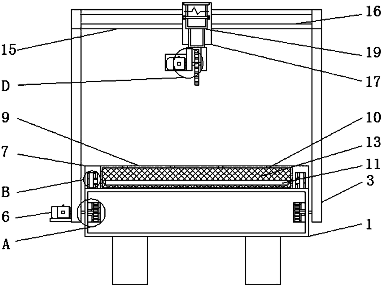
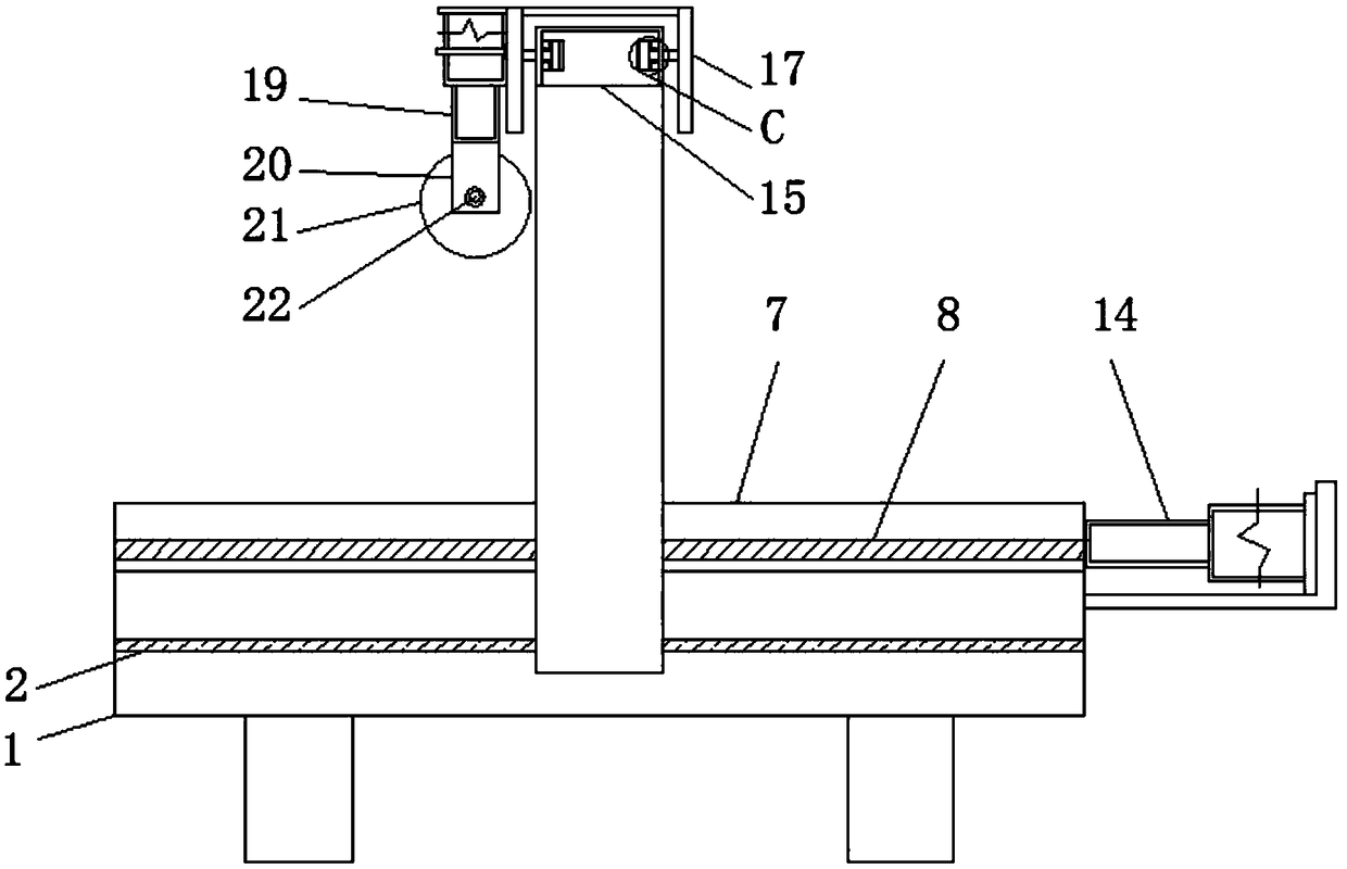
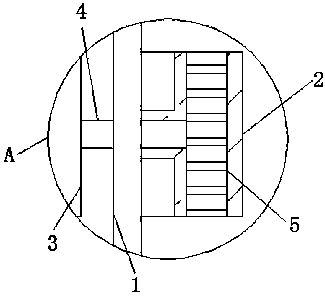
[0022] see Figure 1-6 , the present invention provides a technical solution: a telescopic protective plate for metal cutting devices to prevent iron filings from splashing, according to figure 2 and image 3 As shown, the inside of the workbench 1 is provided with a first chute 2, and the side of the workbench 1 is provided with a support frame 3, the inner surface of the support frame 3 is provided with a first rotating shaft 4, and one end of the first ro...


PUM


Abstract

The invention discloses a scrap iron splashing preventing telescopic protective plate of a metal cutting device. The scrap iron splashing preventing telescopic protective plate comprises a workbench,a first motor, a second baffle and a second hydraulic device; a first sliding groove is formed in the workbench; a first rotation shaft is arranged on the inner side face of a support frame, and a first roller is arranged at one end of the first rotation shaft; the first motor is arranged on the left side face of the support frame; fixing plates are arranged on the upper side face of the workbench; cutting seams are formed in the upper surface of a first baffle; a second roller is arranged on the side face of a transporting plate, the second baffle is arranged on one side of the transporting plate, and first hydraulic devices are arranged on the other side of the transporting plate; a third roller is arranged on the inner side face of a first fixing frame; the second hydraulic device is arranged on the outer side face of the first fixing frame; and a second rotation shaft is arranged in a grinding wheel. According to the scrap iron splashing preventing telescopic protective plate of the metal cutting device, the first baffle is arranged, and therefore metal chips generated through cutting are all blocked on a metal plate through the first baffle.

Description

technical field [0001] The invention relates to the technical field of metal cutting devices, in particular to a telescopic protective plate for metal cutting devices to prevent iron filings from splashing. Background technique [0002] The metal cutting device is a device used to cut metal products. There are some problems with the metal cutting device used in the factory. The current metal cutting device will produce metal shavings when the fast rotating grinding wheel contacts the metal plate during cutting. Metal shavings will splash around, and when the metal shavings splash on the operator, it will cause harm to the operator's body, and when the splashed metal shavings splash on the flammable objects, it will cause unimaginable consequences, and the current cutting device When cutting, it is necessary to manually push the support frame to move, so that the grinding wheel can move and cut, which is very time-consuming and wastes manpower. Therefore, a telescopic protect...

Claims


Application Information

Patent Timeline
IPC IPC(8): B24B27/06B24B27/00B24B55/06B24B47/06B24B41/06
CPCB24B27/06B24B27/0015B24B41/06B24B47/06B24B55/06
Inventor 宋和云
Owner 东至县科创塑料制品有限公司
Learn More