
Safe fixing mechanism of building fire escape forced landing device

A fixed mechanism, fire technology, applied in life-saving equipment, building rescue, etc., can solve problems such as rising unsafe factors, falling off walls, limited load-bearing capacity, etc.

Active Publication Date: 2018-12-21
SHENZHEN WEIXINGSHUN TECH CO LTD
View PDF6 Cites 2 Cited by
  • Summary
  • Abstract
  • Description
  • Claims
  • Application Information

AI Technical Summary

Problems solved by technology

The former is set on the load-bearing wall and cannot be moved. When a fire occurs, it cannot be ensured that the position where the escape device is installed is the best escape position, which will easily lead to empty escape equipment, and it is necessary for the escape personnel to know where the escape device is installed. And it is necessary for the escape personnel to reach the position, but in the actual fire scene, there are great uncertainties in these, which is not conducive to the escape of the fire scene personnel.
The latter is hung on the edge of the window, which solves the problem of the former setting being movable. However, in the current building structure, the windows and other places where the vents are set are not load-bearing walls, and their load-bearing capacity is limited. Among them, the weight of the escape personnel is different, and there are unstable factors such as the vibration and swing of the escape equipment during the escape process, which may easily cause the wall used to fix the window to fall off or the escape equipment itself will fall from the window or the window due to unstable factors such as vibration and swing. Falling off on other outlets, leading to rising insecurity

Method used


Image

  • Safe fixing mechanism of building fire escape forced landing device
  • Safe fixing mechanism of building fire escape forced landing device
  • Safe fixing mechanism of building fire escape forced landing device

Examples


Embodiment Construction

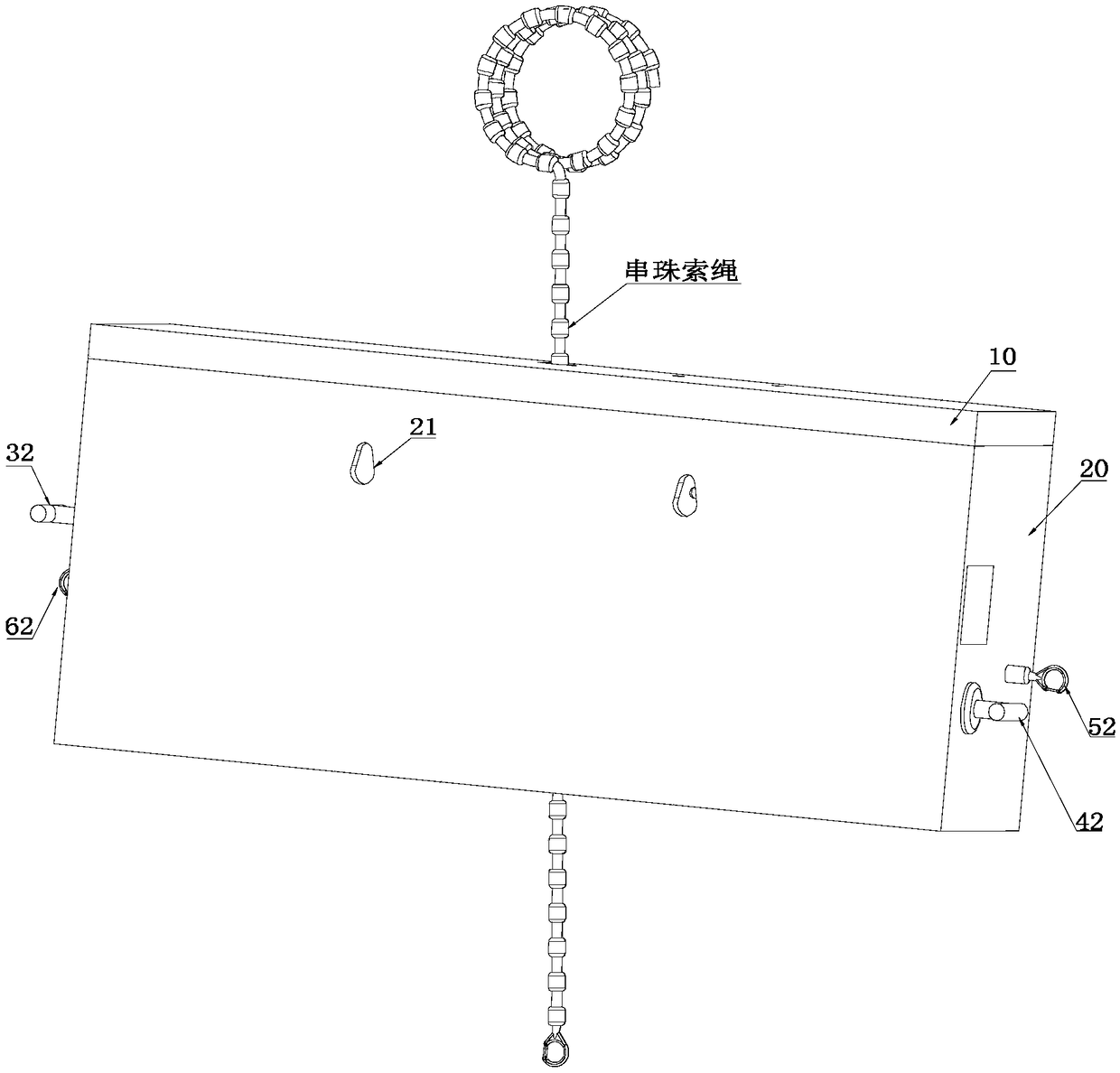
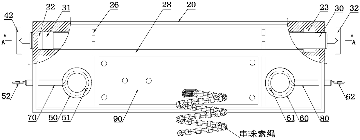
[0030] In this patent document, the following discussed Figure 1-10 The various examples and examples used to describe the principles or methods of the present disclosure are by way of illustration only and should not be construed in any way to limit the scope of the present disclosure. Those skilled in the art should understand that the principles and methods of the present disclosure may be implemented in any suitably arranged mechanical structure. Preferred embodiments of the present disclosure will be described below with reference to the accompanying drawings. In the following description, detailed descriptions of well-known functions or configurations will be omitted so as not to obscure the subject matter of the present disclosure with unnecessary detail. Also, the terms used herein will be defined according to the functions of the present invention. Therefore, the terms may be different according to user's or operator's intention or usage. Therefore, the terms used...


PUM


Abstract

The invention relates to a safe fixing mechanism of a building fire escape forced landing device. The safe fixing mechanism comprises a box body and a fixing rod. The fixing rod is arranged in the boxbody and is in sliding connection with the box body. One end portion of the fixing rod is provided with a locking part. The box body is internally provided with a sliding passage and a locking groove, wherein the sliding passage is in sliding connection with the locking part, and the locking groove is arranged at one end of the sliding passage and is used for forming a locking mechanism togetherwith the locking part. A shell of the box body is provided with a hole communicating with the locking groove. The fixing rod is in sliding connection with the hole wall of the hole. When the locking part is locked with the locking groove, the fixing rod is pulled out and arranged outside the box body, and forms an anchor-shaped mechanism together with the box body to increase the passing area of the building fire escape forced landing device. Therefore, the building fire escape device can move flexibly, and more fixing structures are added to be connected with indoor fixed objects at the sametime to improve the safety performance of the building fire escape device.

Description

technical field [0001] The invention relates to the field of security technology, in particular to a safety fixing mechanism of a building fire escape forced landing device. Background technique [0002] Disclaimer: Throughout this specification, any discussion of background art should in no way be considered an acknowledgment that such art is well known, or forms part of the common general knowledge in the art. [0003] At present, there are mainly two ways of fixing traditional building fire escape forced landing devices in actual use. One is the non-removable fixed way fixed on the load-bearing wall, and the other is the movable way hung on the edge of the window. The former is set on the load-bearing wall and cannot be moved. When a fire occurs, it cannot be ensured that the position where the escape device is installed is the best escape position, which will easily lead to empty escape equipment, and it is necessary for the escape personnel to know where the escape dev...

Claims


Application Information

Patent Timeline
IPC IPC(8): A62B1/06A62B1/18
CPCA62B1/06A62B1/18
Inventor 利友荣
Owner SHENZHEN WEIXINGSHUN TECH CO LTD
Learn More