A constant pressure liquid injection device and a liquid injection method for a square power battery
A liquid injection device and power battery technology, applied in secondary batteries, battery pack components, circuits, etc., can solve problems such as affecting the life of battery fixtures, polluting the working environment, and uneven electrolyte dispersion.
- Summary
- Abstract
- Description
- Claims
- Application Information
AI Technical Summary
Problems solved by technology
Method used
Image

Examples
Embodiment 1
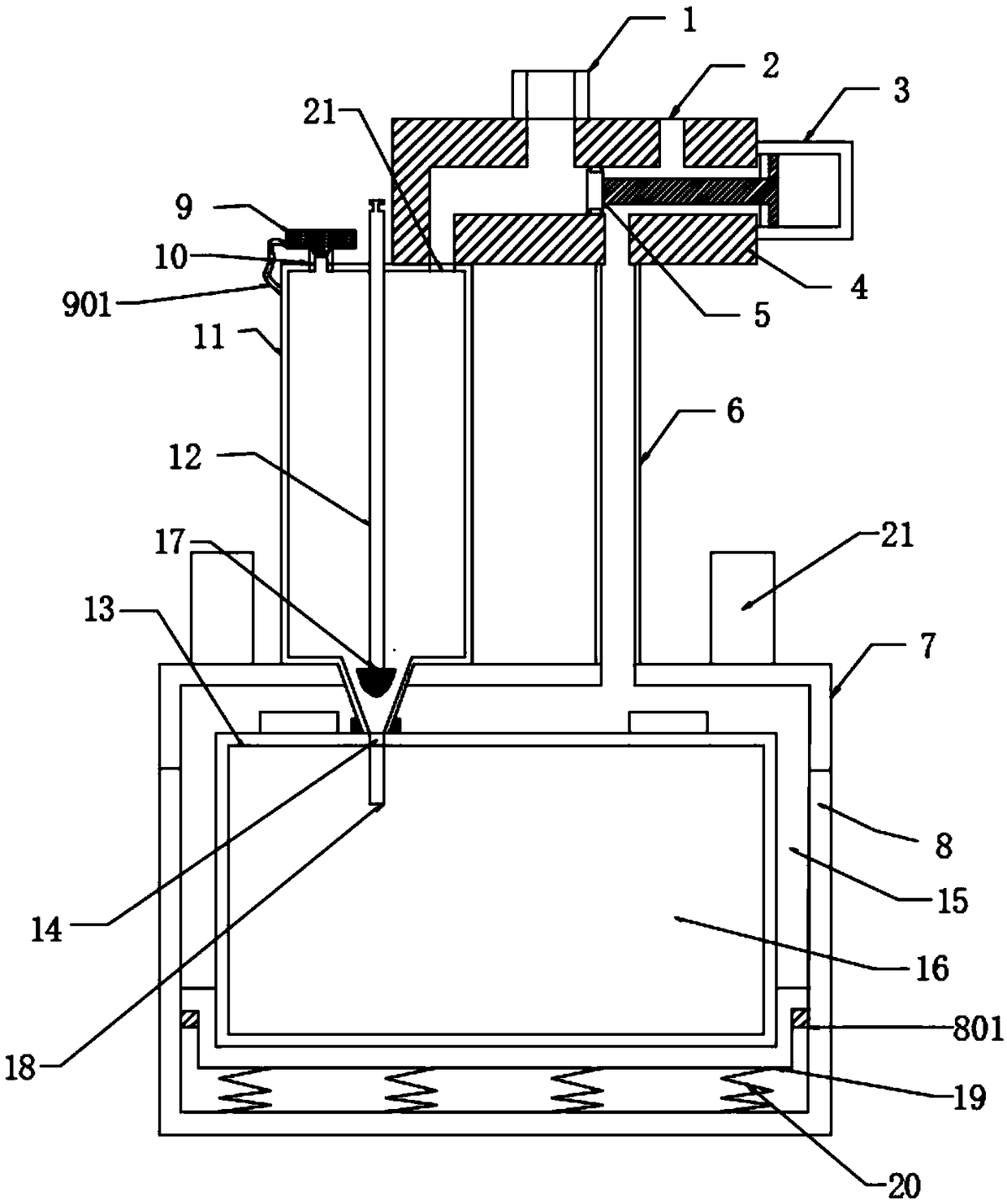
[0047] like Figure 1-3 As shown, a square power battery constant pressure liquid injection device includes a liquid injection device and a fixture, and the fixture includes a fixture upper cover 7 and a fixture lower cover 8, and the fixture upper cover 7 and the fixture lower cover 8 are separate structures , the detachable structure can be, but not limited to, by setting locks on the fixture upper cover 7 and the fixture lower cover 8, and at the same time, a rubber pad is provided at the opening and closing of the fixture upper cover 7 and the fixture lower cover 8, and when closed, it is Lock the sealed state and form a clamp inner cavity 15, which is used to fix the battery 13, and the battery 13 includes a battery liquid injection hole 14 and a battery inner cavity 16; the liquid injection device is fixedly connected to the upper part of the clamp surface;
[0048] The liquid injection device includes a liquid injection cup 11, the top of the liquid injection cup 11 is...
Embodiment 2
[0055] like Figure 4-5 As shown, this embodiment is further optimized on the basis of Embodiment 1. Specifically, the anti-drip assembly 18 includes a fixed disc 1801, and the fixed disc 1801 is provided with through holes 1802 on its circumference. A hose 1803 integrally injection-molded with the through hole 1802 is provided under the disc 1801, and an elbow 1804 is provided under the hose 1803, and at least four hoses 1803 are provided, and each elbow 1804 is The radial distribution of the circumference away from the center of the circle, the output end 1805 of the elbow is located on the same horizontal plane, and the elbow 1804 is provided with reinforcing ribs to improve the mechanical performance of the elbow. During positive and negative pressure injection, the impact of the injection pressure on the hose 1803 will cause the electrolyte to form a dispersed injection. After the injection is stopped, due to the performance of the material of the hose 1803, the elbow 180...
Embodiment 3
[0057] like Figure 6-7 As shown, this embodiment is further optimized on the basis of Embodiment 1. Specifically, the anti-drip component 18 includes a liquid injection nozzle 1806 that matches the liquid injection nozzle, and the liquid injection nozzle 1806 can be It is fixed by thread and can be replaced in time. The inner wall of the liquid injection pipe head 1806 is provided with a fixed rod 1811, and the fixed rod 1811 is perpendicular to the inner wall of the liquid injection pipe head 1806. Rod 1807, the rotating rod 1807 can rotate at the center of the fixed rod, the axial side wall of the rotating rod 1807 is hinged with a combined piece, and the combined piece includes at least three blades 1808, and the blades 1808 are inclined to one side. When the electrolyte is in contact with the combined sheet, the force generated by the impact of the electrolyte on the combined sheet makes the rotating rod 1807 rotate to generate centrifugal force, and the electrolyte is th...
PUM
 Abstract
Description
Claims
Application Information
 - R&D
- Intellectual Property
- Life Sciences
- Materials
- Tech Scout
- Unparalleled Data Quality
- Higher Quality Content
- 60% Fewer Hallucinations
Browse by: Latest US Patents, China's latest patents, Technical Efficacy Thesaurus, Application Domain, Technology Topic, Popular Technical Reports.
© 2025 PatSnap. All rights reserved.Legal|Privacy policy|Modern Slavery Act Transparency Statement|Sitemap|About US| Contact US: help@patsnap.com