
Light supplementing lens, light supplementing lamp and camera

A lens and supplementary light technology, applied in the field of supplementary lights, cameras, and supplementary light lenses, can solve the problems of inability to achieve supplementary light, small microstructure size, lack of flexibility, etc., to achieve high optical efficiency and energy utilization efficiency, optical Simple device structure and good flexibility

Active Publication Date: 2018-12-18
HANGZHOU HIKVISION DIGITAL TECH
View PDF9 Cites 11 Cited by
  • Summary
  • Abstract
  • Description
  • Claims
  • Application Information

AI Technical Summary

Problems solved by technology

[0004] One of the rectangular light distribution technologies is a rotationally symmetric total reflection plus corrugated or microstructure scheme, that is, corrugated or microstructures are arranged on the exit surface of the lens to distribute the collimated light reflected by the reflective surface and transmitted by the mold core in a rectangular shape. The light distribution technology cannot achieve a large angle range of supplementary light, and with the increase of the supplementary light range, the attenuation of the lens transmittance is intensified, and limited by the production technology, the microstructure size is small and the tolerance is small, which is not conducive to product consistency. Seriously affect the performance stability of the product
[0005] Another rectangular light distribution technology is a combination of separate reflective free-form surfaces (reflector cups) and a lens solution. This type of light distribution technology lacks flexibility and the overall optical efficiency is low
Moreover, the reflector and the lens are separate devices. In order to ensure the accuracy of the assembly of the separate devices, the production cost will be greatly increased, and the stability of the product is poor.

Method used


Image

  • Light supplementing lens, light supplementing lamp and camera
  • Light supplementing lens, light supplementing lamp and camera
  • Light supplementing lens, light supplementing lamp and camera

Examples


Embodiment Construction

[0039] In order to make the technical solutions and advantages of the present invention clearer, the embodiments of the present invention will be further described in detail below in conjunction with the accompanying drawings.

[0040]In the present application, the terms "first", "second" and so on are used for descriptive purposes only, and cannot be interpreted as indicating or implying relative importance or implicitly specifying the quantity of indicated technical features. In the present application, the term "area" generally refers to a range on a plane or a curved surface relative to a plane or a curved surface, and generally refers to a range on a three-dimensional space relative to a space. In this application, the fill light space area is generally cone-shaped; the term "preset fill light plane" generally refers to the centerline of the cone-shaped fill light space area perpendicular to the fill light lens (it can also be roughly considered as the corresponding lens ...


PUM


Abstract

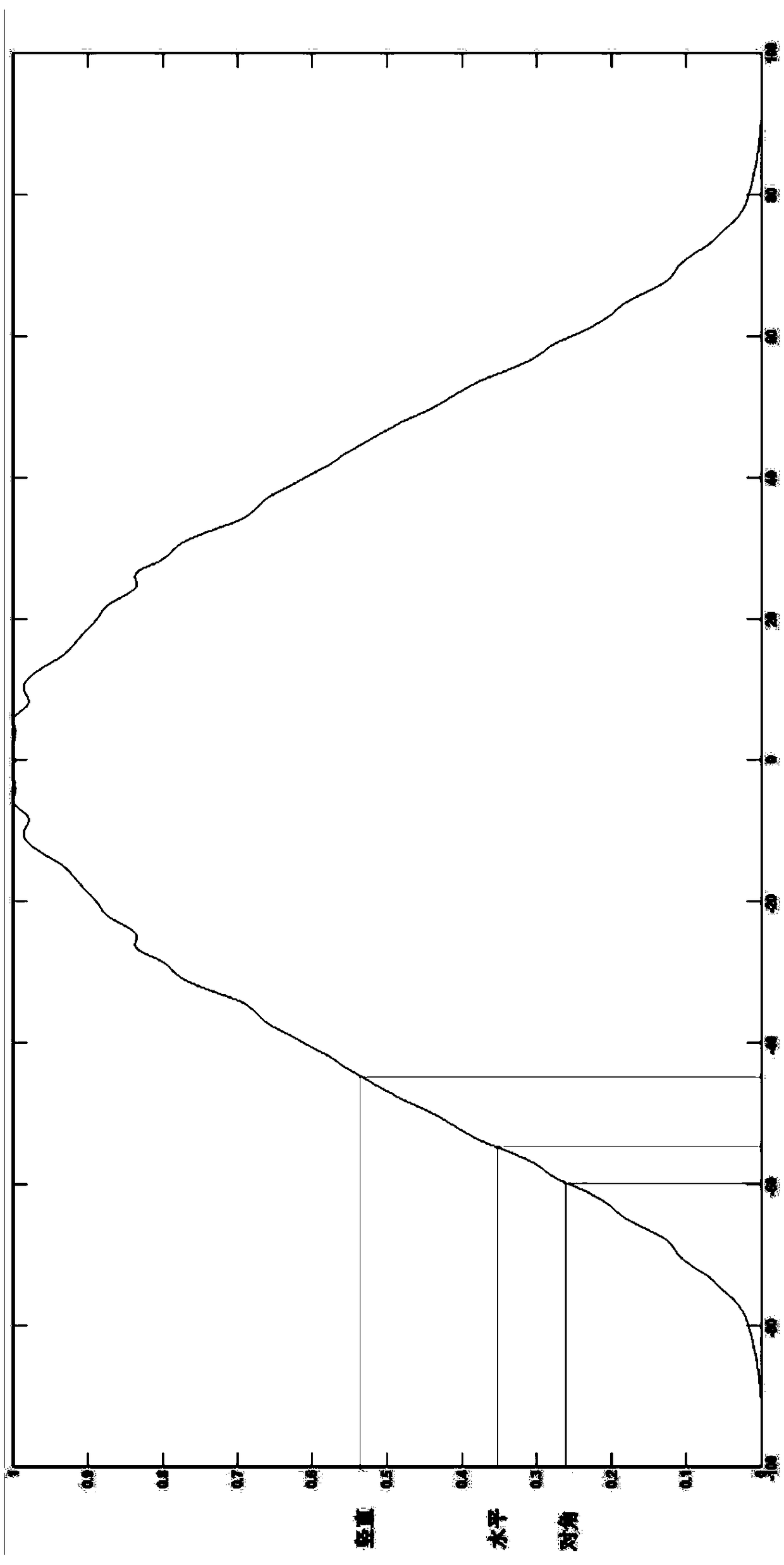
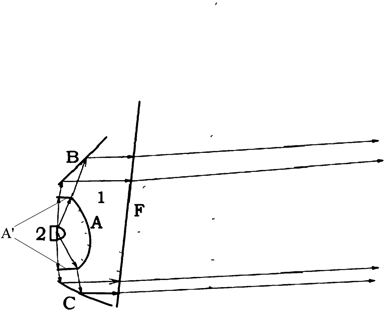
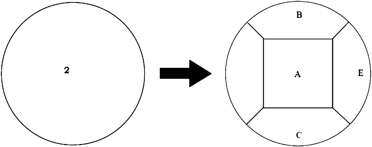
The invention provides a light supplementing lens, a light supplementing lamp and a camera. The light supplementing lens comprises an incidence curved face, a reflection curved face and an emergent smooth curved face. The incidence curved face comprises a free transmission curved face and an inner side wall, wherein the inner side wall is located on the periphery of the free transmittance curved face and is adjacent to the free transmission curved face. The reflection curved face comprises one or more free reflection curved faces, wherein each free reflection curved face corresponds to one section, in the circumferential direction, of the inner side wall. The light supplementing lens is configured that when a matched light source is located in a preset relative position and is used together with the light supplementing lens, a light supplementing area of a target rectangle is formed on a preset light supplementing plane. By means of the light supplementing lens, the light supplementinglamp and the camera, high optical efficiency and energy utilization efficiency are achieved, and light supplementing of a large angle range can be achieved.

Description

technical field [0001] The invention relates to the technical field of video monitoring, in particular to a supplementary light lens, a supplementary light and a video camera. Background technique [0002] In video surveillance, in order to make up for the lack of light at night, an infrared supplementary light is usually installed on the surveillance camera to provide supplementary light within the camera's lens field of view, thereby improving the brightness and clarity of the camera's lens picture and making it easy to identify people. or object. [0003] The photosensitive area of ​​the image sensor that determines the shape of the lens picture of the surveillance camera is a rectangular area of ​​16:9 or 4:3. If a rotationally symmetrical light distribution scheme with a roughly circular cross section is adopted, in order to satisfy the captured lens picture without dark areas For vignetting, the angle of fill light is generally set to be slightly larger than the diago...

Claims


Application Information

Patent Timeline
IPC IPC(8): F21S8/00F21V5/04F21V13/04G02B5/126G03B15/06
CPCG03B15/06F21S8/00F21V5/04F21V13/04G02B5/126
Inventor 唐海龙
Owner HANGZHOU HIKVISION DIGITAL TECH
Learn More