
Composite water discharging system of waste mineral oil

A technology of drainage system and waste mineral oil, applied in waterway system, sewage removal, water supply device, etc., can solve the problems of inability to complete the replacement of the filter screen, the drainage system cannot be used immediately, and the blockage of solid materials, etc.

Active Publication Date: 2018-12-18
HEILONGJIANG LAIRUIPUSI ENVIRONMENTAL TECH DEV CO LTD
View PDF6 Cites 4 Cited by
  • Summary
  • Abstract
  • Description
  • Claims
  • Application Information

AI Technical Summary

Problems solved by technology

[0004] When the current drainage system discharges the waste minerals and oil pollution of the waste mineral oil separation, there will be solid substances blocked into the drainage pipe, which will cause the drainage system. Therefore, the existing methods are to prevent excessive or Excessive waste minerals block the inside of the drain pipe, so that even if the blockage occurs, it is outside the drain pipe. At this time, the staff only need to replace the filter screen to solve the blockage problem, but when replacing the filter screen, there will be The following problems: first, when replacing the filter screen, the staff first needs to remove the waste minerals on the filter screen surface, and then take out the old filter screen. It is usually carried out by tightening or loosening the bolts on it, and in the drainage system, the filter screen needs to be replaced regularly, which is inconvenient to take out; secondly, after taking out the old filter screen, the new filter screen needs to be replaced Place the original filter on the original position of the old filter. At this time, the staff must carry the filter that can be replaced. If the filter that needs to be replaced is not carried, the replacement of the filter cannot be completed, resulting in the drainage system not available immediately

Method used


Image

  • Composite water discharging system of waste mineral oil
  • Composite water discharging system of waste mineral oil
  • Composite water discharging system of waste mineral oil

Examples


specific Embodiment approach

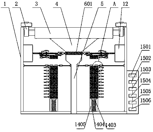
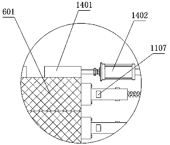
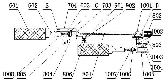
[0038] The specific implementation is as follows: in the process of use, when the waste minerals and oil stains separated from the waste mineral oil enter the sump 3 from the drain pipe 2, they are collected from the sump 3 to the sump 4, and the sump 4 The filter screen 601 on the screen will isolate the solid impurities of the waste mineral oil on its surface. For a long time, the solid impurities with a larger or equal diameter than the through holes of the filter screen 601 will be stuck in the through holes or in the filter screen 601. On the surface, at this time, it is necessary to replace the filter screen 601. When replacing it, the staff first controls the rotation of the motor A802 through the controller 1505, and the rotation of the motor shaft of the motor A802 drives the screw rod connected to it. The rotation of A801 ​​drives the rotation of the screw slider A703 connected to it through the rotation of the screw A801, the movement of the screw slider A703 drives ...


PUM


Abstract

The invention provides a composite water discharging system of waste mineral oil and relates to the technical field of water discharging systems. The water discharging system comprises a water discharging geosyncline, a water discharging pipe, a water collection groove, a water gathering groove and a flowing channel. A filtering net mechanism, a filtering net moving mechanism, a sliding mechanism,a touch mechanism, a changing mechanism, a clamping mechanism, a protection case, a moving mechanism, a material placing mechanism and a control mechanism are arranged in the water discharging geosyncline. According to the invention, it is quick and convenient to change the filtering net; there is no need for workers to be involved in the whole processes too much; the system is suitable for waterdischarging system where the filtering net should be periodically replaced; there is no need for workers to carry new filtering nets at any time; after a new filtering net is replaced, a new filtering mechanism can be taken out from the material placing mechanism to replace the filtering mechanism; the filtering net is quick and convenient to replace; and the system is suitable for application inthe current composite water discharging system of waste mineral oil.

Description

technical field [0001] The invention relates to the technical field of drainage systems, in particular to a waste mineral oil comprehensive drainage system. Background technique [0002] Waste mineral oil mainly comes from oil sludge and oil feet produced by oil exploitation and refining, sediment produced in the storage of mineral oil, oil residue and filter media in the replacement of oil and regeneration of machinery, power, transportation and other equipment, etc. . The "National Hazardous Waste List" classifies waste mineral oil as hazardous waste. Various components in waste mineral oil have toxic effects on the human body, such as 3,4-benzopyrene, polychlorinated biphenyl (PCB), which have strong carcinogenic effects. ), etc., once a large amount enters the external environment, it will destroy the biological habitat, endanger the safety of animals, plants and human bodies, and cause serious environmental pollution. Therefore, the treatment and disposal of waste min...

Claims


Application Information

Patent Timeline
IPC IPC(8): E03F1/00B01D29/01C10G31/09
CPCB01D29/01C10G31/09E03F1/00
Inventor 刘潇李云凌
Owner HEILONGJIANG LAIRUIPUSI ENVIRONMENTAL TECH DEV CO LTD
Learn More