A high-efficiency printing and dyeing treatment system and process for textile fabrics
A technology for textile fabrics and processing systems, which is applied in the directions of spray/jet textile material processing, textile material processing equipment configuration, etc., can solve the problems of uneven dyeing, low dye utilization rate, poor dyeing effect, etc. The effect of improving the utilization rate and improving the uniformity of dyeing
- Summary
- Abstract
- Description
- Claims
- Application Information
AI Technical Summary
Problems solved by technology
Method used
Image
Examples
Embodiment 1
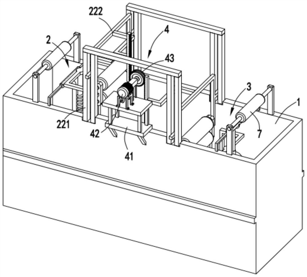
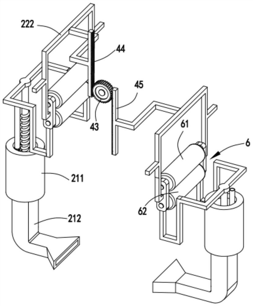
[0052] Such as Figure 1 to Figure 12 As shown, a high-efficiency printing and dyeing treatment system for textile fabrics includes a dye box 1, in which a first dyeing mechanism 2 and a second dyeing mechanism 3 are sequentially arranged in the dye box 1, and the first dyeing mechanism 2 and the second dyeing mechanism 3 both include a filtrate assembly fixed on the inner wall of the dye box 1, a squeeze grinding assembly arranged in the filtrate assembly, and a spraying assembly arranged at the upper end of the filtrate assembly;
[0053] A driving mechanism 4 is arranged between the first dyeing mechanism 2 and the second dyeing mechanism 3, and the driving mechanism 4 is used to drive the front and rear extrusion grinding assemblies to alternately lift up and down, and the front and rear extrusion grinding assemblies When the assembly moves upwards, the filtrate assembly draws the dye solution at the bottom of the dye box 1, and when the front and rear extrusion grinding a...
Embodiment 2
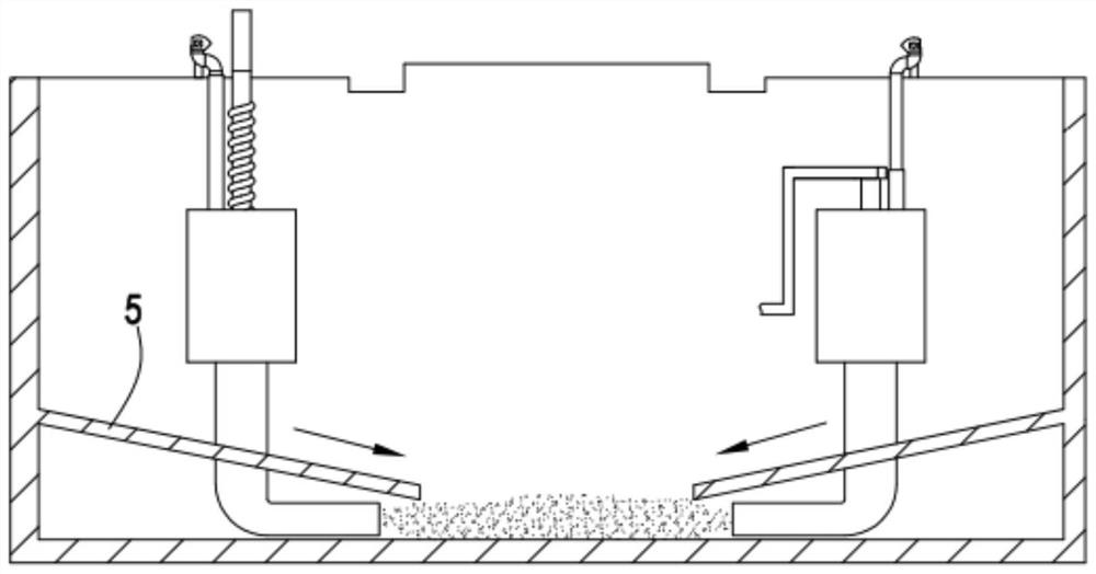
[0070] Such as figure 2 As shown, the components that are the same as or corresponding to those in the first embodiment are marked with the corresponding reference numerals in the first embodiment. For the sake of simplicity, only the differences from the first embodiment will be described below. The difference between the second embodiment and the first embodiment is that further, the suction pipe 212 is close to the bottom of the dye tank 1 and its end is bent towards the middle of the bottom of the dye tank 1, and the filtrate assembly is arranged below There is a guide plate 5, the end of which guide plate 5 is inclined downwards towards the middle of the bottom of the dye tank 1 .
[0071] By setting the guide plate 5 at the bottom of the dye box 1, some deposited coarse dyes and impurities travel along the guide plate 5 to the ports of the two suction pipes 212, which improves the efficiency of coarse dye collection and grinding.
Embodiment 3
[0073] Such as Figure 13 As shown, a high-efficiency printing and dyeing process for textile fabrics includes the following production steps:
[0074] (a) Dye liquor extraction process, when the squeeze grinding assembly of the first dye spray mechanism 2 and the second dye spray mechanism 3 moves upward, the dye liquor deposited at the bottom of the dye tank 1 is drawn through the suction pipe 212 into the grinding chamber 211 ;
[0075] (b) a dyeing process, the fabric to be printed and dyed is transported to the top of the first dyeing mechanism 2 through the guide roller 7, and the extrusion grinding assembly of the first dyeing mechanism 2 moves downward to squeeze the dye solution in the grinding chamber 211 , so that the dyeing liquid is sprayed out through the spraying assembly of the first spraying mechanism 2 to spray and dye the fabric once;
[0076] (c) Dip-dyeing process, the once-sprayed fabric is transported between the first dyeing mechanism 2 and the second d...
PUM
 Abstract
Description
Claims
Application Information
 - R&D
- Intellectual Property
- Life Sciences
- Materials
- Tech Scout
- Unparalleled Data Quality
- Higher Quality Content
- 60% Fewer Hallucinations
Browse by: Latest US Patents, China's latest patents, Technical Efficacy Thesaurus, Application Domain, Technology Topic, Popular Technical Reports.
© 2025 PatSnap. All rights reserved.Legal|Privacy policy|Modern Slavery Act Transparency Statement|Sitemap|About US| Contact US: help@patsnap.com


