A mold device

A mold and stamping die technology, applied in the field of mold devices, can solve the problems of shortening the service life of the mold, wear of the mold base, increasing economic costs, etc., and achieve the effects of good buffering and decompression, prolonging service life and simple structure.

Active Publication Date: 2020-04-14
江西省天奇汽车零部件有限公司
View PDF8 Cites 0 Cited by
  • Summary
  • Abstract
  • Description
  • Claims
  • Application Information

AI Technical Summary

Problems solved by technology

[0002] In the traditional mold device, it often includes a mold base, an upper stamping module and a lower stamping module, wherein the upper stamping module continuously cooperates with the lower stamping module for processing. Extrusion, that is, the upper stamping module directly squeezes the mold base, which will cause the mold base to bear too much force, which will cause the mold base to be worn, cause the mold base to be damaged, and shorten the service life of the mold; in addition, the existing Advanced mold equipment often has complex structural defects, resulting in increased economic costs in later maintenance processes

Method used


Image

  • A mold device
  • A mold device
  • A mold device

Examples


Embodiment Construction

[0018] The present invention will be described in further detail below in conjunction with the accompanying drawings and specific embodiments.

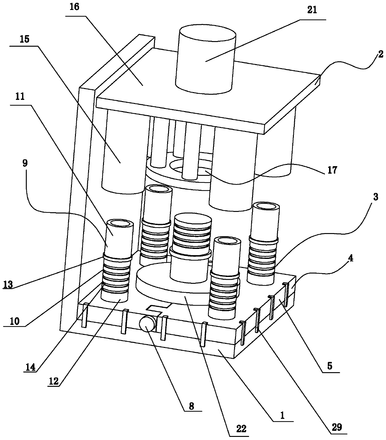
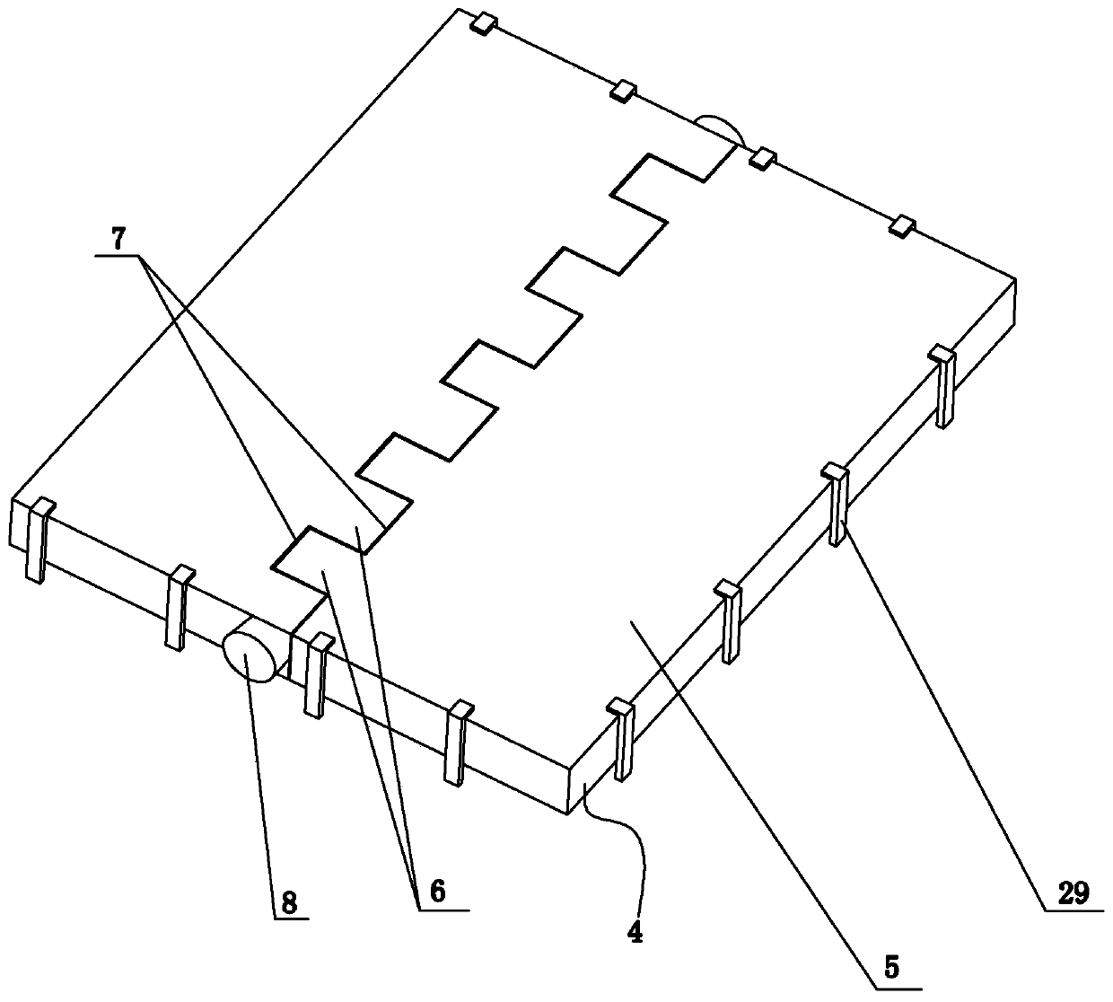
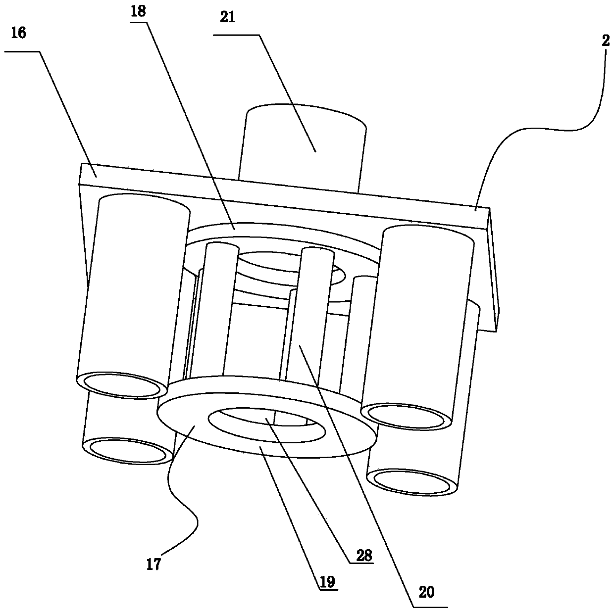
[0019] like figure 1 , figure 2 , image 3 and Figure 4 shown;

[0020] A mold device of the present invention comprises an "L"-shaped frame 1, on which an upper stamping die set 2 and a lower stamping die set 3 are arranged, and a die set clamped between the frame 1 and The buffer mechanism 4 between the lower stamping die sets 3, the buffer mechanism 4 includes two backing plates 5 tightly engaged, one side of the two backing plates 5 is provided with several rectangular racks 6, adjacent A card slot 7 is formed between the two racks 6, and the racks 6 on the two backing plates 5 are arranged alternately, and the two backing plates 5 are tightly engaged and pass through the two backing plates at the same time. The connecting shaft 8 of 5 is fixedly connected. By arranging a buffer mechanism 4 between the frame 1 and the lowe...


PUM


Abstract

The invention discloses a mold device which comprises an L-shaped frame (1). The frame (1) is provided with an upper stamping module (2) and a lower stamping module (3); the mold device further comprises a buffer mechanism (4) clamped between the frame (1) and the lower stamping module (3), the buffer mechanism (4) comprises two base plates (5) which are tightly clamped, one side of each of the two base plates (5) is provided with a plurality of rectangular gear racks (6), a clamping groove (7) is formed between every two adjacent gear racks (6), the gear racks (6) on the two base plates (5) are staggered, and the two base plates (5) are fixedly connected through a connecting shaft (8) which simultaneously penetrates the two base plates (5) after the two base plates (5) are tightly clamped. The mold device is simple in structure, and the service life of the mold device can be prolonged.

Description

technical field [0001] The invention relates to the technical field of mechanical equipment, in particular to a mold device. Background technique [0002] In the traditional mold device, it often includes a mold base, an upper stamping module and a lower stamping module, wherein the upper stamping module continuously cooperates with the lower stamping module for processing. Extrusion, that is, the upper stamping module directly squeezes the mold base, which will cause the mold base to bear too much force, which will cause the mold base to be worn, cause the mold base to be damaged, and shorten the service life of the mold; in addition, the existing Advanced mold equipment often has complex structure defects, which leads to an increase in economic costs in the later maintenance and other processes. Contents of the invention [0003] The technical problem to be solved by the present invention is to overcome the above defects of the prior art and provide a mold device with s...

Claims


Application Information

Patent Timeline
Patent Type & Authority Patents(China)
IPC IPC(8): B21D37/10B21D37/18B21D55/00
CPCB21D37/10B21D37/18B21D55/00
Inventor 郭明方
Owner 江西省天奇汽车零部件有限公司
Why Eureka
Try Eureka