Temperature-variable isothermal shift reactor

An isothermal transformation and reactor technology, applied in chemical instruments and methods, chemical/physical processes, etc., can solve problems such as strict equipment requirements, reduced heat transfer coefficient of heat exchange tubes, increased pressure of steam drums and heat exchange tubes, etc. , to avoid difficult control, reduce equipment investment, and achieve the effect of constant yield

Inactive Publication Date: 2018-12-18
SINOPEC NINGBO ENG +2
View PDF7 Cites 2 Cited by
  • Summary
  • Abstract
  • Description
  • Claims
  • Application Information

AI Technical Summary

Problems solved by technology

[0005] However, as the reaction progresses, the activity of the catalyst decreases, leading to an increase in the catalyst's active temperature, from about 240°C in the initial stage to about 280°C, which requires the reaction temperature to increase accordingly.
The current solution to this problem is usually to increase the temperature of cooling water and heat exchange steam in the later stage of the reaction, which will inevitably lead to a sharp increase in the pressure in the steam drum and heat exchange tubes; at the same time, the design wall thickness of the steam drum and heat exchange tubes should be increased accordingly
In addition to strict requirements on equipment, this will also lead to a series of other problems. For example, due to the increase in the wall thickness of the heat exchange tube, the heat transfer coefficient of the heat exchange tube will decrease, and the amount of heat exchange in the early stage of the reaction will also need to increase; and, Due to changes in the temperature and pressure of the outlet steam drum, it will inevitably lead to corresponding changes in supporting pipelines and equipment

Method used


Image

  • Temperature-variable isothermal shift reactor
  • Temperature-variable isothermal shift reactor
  • Temperature-variable isothermal shift reactor

Examples


Embodiment Construction

[0026] The present invention will be further described in detail below in conjunction with the accompanying drawings and embodiments.

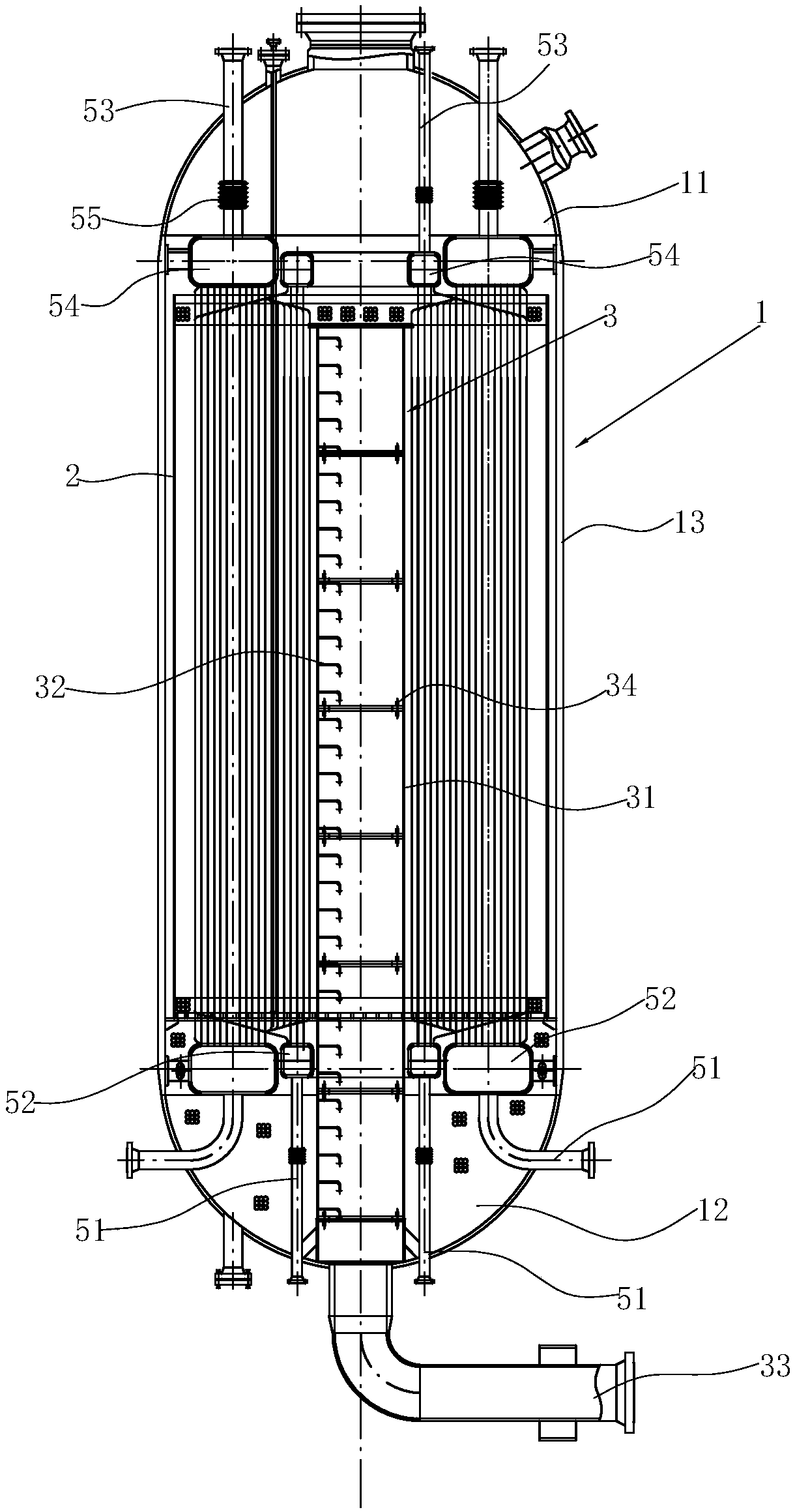
[0027] Such as Figure 1 to Figure 3 Shown, this variable temperature isothermal shift reactor comprises:

[0028] The furnace body 1 is a conventional structure, including an upper head 11 , a lower head 12 and a cylinder 13 connected between the upper head 11 and the lower head 12 .

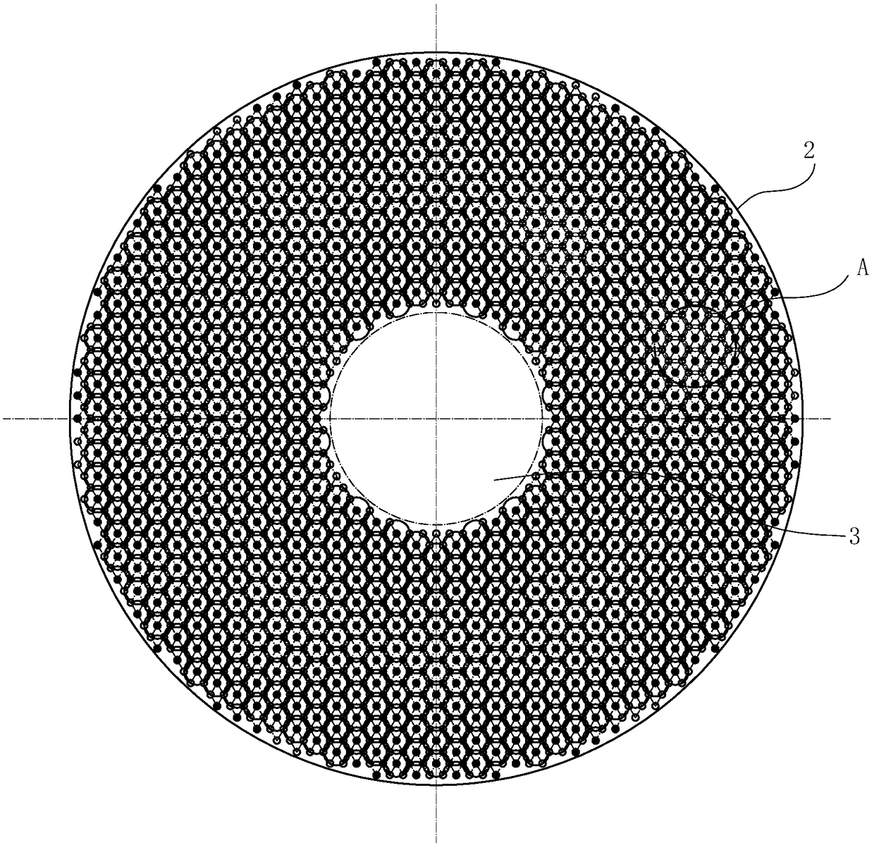
[0029] The catalyst frame 2 is used for loading catalyst and is arranged in the cylinder body 13 . The catalyst frame 2 can be any one of the prior art according to the needs, for example, it can be an axial reactor, it can also be a radial reactor, or it can also be an axial radial reactor, which can be set according to the needs. This embodiment is a radial reactor, and the feed gas enters the catalyst frame from the side wall of the catalyst frame 2 .

[0030] The synthesis gas collection pipe 3 is used to collect the synthesis gas and send the synthesis ...


PUM


Abstract

The invention relates to a temperature-variable isothermal shift reactor, comprising a furnace body, a catalyst frame, a syngas collecting pipe and a heat exchange pipe, wherein an inlet and an outletof the heat exchange pipe are respectively connected to water inlet pipelines and a steam pipeline; the variable temperature isothermal shift reactor is characterized in that the heat exchange pipe comprises a first heat exchange pipe group consisting of multiple first heat exchange pipes and a second heat exchange pipe group consisting of multiple second heat exchange pipes; wherein the cross section of each first heat exchange tube along the catalyst frame is evenly arranged in a cavity between the catalyst frame and the syngas collecting pipe; each second heat exchange pipe is evenly arranged along the outer circumference of the respective corresponding first heat exchange tube, and at least three second heat exchange tubes are evenly arranged around each first heat exchange pipe; twowater inlet pipelines are provided, and each water inlet pipeline is provided with a valve; inlets of all the first heat exchange pipes are communicated to the first water inlet pipe, inlets of all the second heat exchange pipes are communicated to the second water inlet pipe; outlets of the first heat exchange pipes and outlets of the second heat exchange pipes are both communicated to the steampipeline.

Description

technical field [0001] The invention relates to chemical equipment, in particular to an isothermal shift reactor. Background technique [0002] CO shift reaction It is an exothermic reaction. The temperature of the fully reacted shift gas can reach about 450°C, but the energy barrier (reactivity energy) of the reaction is relatively high. Before the reaction, the reaction raw material, namely crude gas, needs to be heated to 260°C or higher. temperature. Therefore, the previous shift process uses the shift gas and crude gas heat exchanger, which uses the shift gas with higher temperature generated after the shift reaction to exchange heat with the raw gas before the shift reaction. A large amount of energy can be saved, and at the same time, the reaction rate and efficiency can be greatly improved. However, because the outlet temperature of the converter is very high, the pressure of the conversion reaction is very high, usually 3-6 MPa, which puts forward higher require...

Claims


Application Information

Patent Timeline
Patent Type & Authority Applications(China)
IPC IPC(8): B01J8/02B01J8/00
CPCB01J8/001B01J8/02
Inventor 张志国蒋自平方晓峰许仁春高步新崔金栋刘复民张茹应超楼力行
Owner SINOPEC NINGBO ENG
Why Eureka
Try Eureka