
High temperature refining furnace used for metallurgy worker and provided with internal protection structure

A protective structure and high temperature technology, applied in the direction of furnace, charge, crucible furnace, etc., can solve the problems of uneven heat, poor metal smelting effect, insufficient supplementary heat, etc., to ensure the preparation quality, uniform heat distribution, and effective transmission hot effect

Inactive Publication Date: 2018-12-14
ANHUI UNIVERSITY OF TECHNOLOGY AND SCIENCE
View PDF0 Cites 4 Cited by
  • Summary
  • Abstract
  • Description
  • Claims
  • Application Information

AI Technical Summary

Problems solved by technology

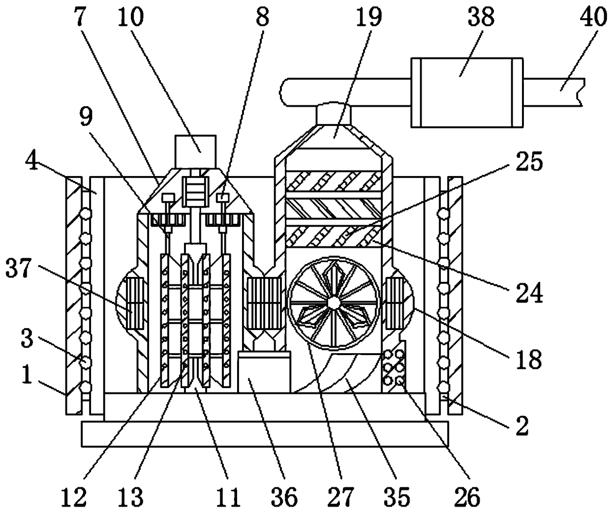
[0004] The purpose of the present invention is to provide a metallurgical high-temperature smelting furnace with an internal protective structure, so as to solve the problem that the modern smelting furnace proposed in the background technology does not have smelting periodicity and transition in the smelting process. In the process of processing, the heat is often not uniform enough and the supplementary heat is not strong enough, which leads to the uneven heating of the metal smelting process. There is no other heating structure inside the refining furnace, resulting in insufficient heat supply in the later stage of refining. The problem of poor metal smelting effect

Method used


Image

  • High temperature refining furnace used for metallurgy worker and provided with internal protection structure
  • High temperature refining furnace used for metallurgy worker and provided with internal protection structure
  • High temperature refining furnace used for metallurgy worker and provided with internal protection structure

Examples


Embodiment Construction

[0028] The following will clearly and completely describe the technical solutions in the embodiments of the present invention with reference to the accompanying drawings in the embodiments of the present invention. Obviously, the described embodiments are only some, not all, embodiments of the present invention. Based on the embodiments of the present invention, all other embodiments obtained by persons of ordinary skill in the art without making creative efforts belong to the protection scope of the present invention.

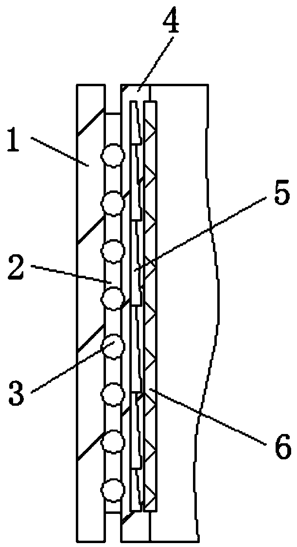
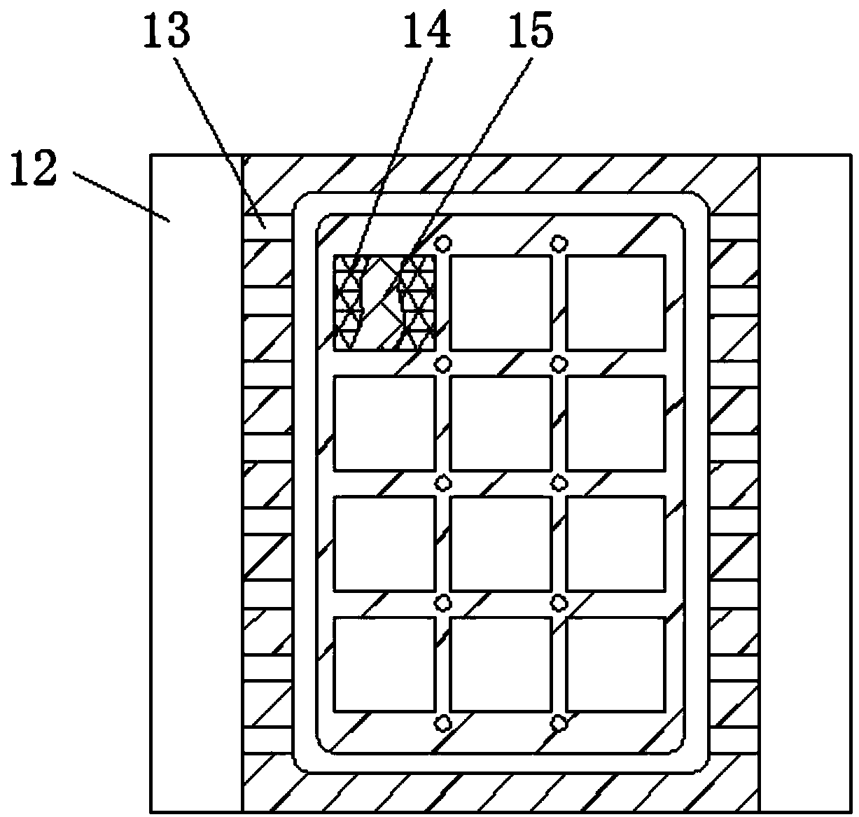
[0029] see Figure 1-7, the present invention provides a technical solution: a metallurgical high-temperature refining furnace with an inner protective structure, including an outer guard plate 1 and a heat relay furnace 7, the inner wall of the outer guard plate 1 is fixed with a middle transition plate 2, and the middle The inside of the transition plate 2 is provided with a lining plate 4, and the inside of the intermediate transition plate 2 is provided wi...


PUM


Abstract

The invention discloses a high temperature refining furnace used for a metallurgy worker and provided with an internal protection structure. The high temperature refining furnace comprises an outer protection plate and a heat relaying furnace, a middle transition plate is fixed to the inner wall of the outer protection plate, an interior lining panel is arranged on the inner side of the middle transition plate, a controller box is installed above the interior of the heat relaying furnace, and the heat relaying furnace is located on the inner side of the interior lining panel. According to thehigh temperature refining furnace used for the metallurgy worker and provided with the internal protection structure, a circulation pipe and the interior lining panel are arranged, temperature insideequipment can be stored and used in a circulated manner, it is guaranteed that the temperature inside the equipment is in the relatively-constant state, hot airflow is led into the circulation pipe, auxiliary heating is carried out on the interior of the equipment, hot flow inside the circulation pipe can be heat generated by refining metal by the equipment, after primary refining is finished, theheat can spirally flow through the circulation pipe, constant-temperature protection on the interior of the equipment is carried out, a metal heat transferring plate can achieve effective heat transferring, constant-heating cotton layers enable the heat to be emitted more evenly.

Description

technical field [0001] The invention relates to the technical field of metallurgical refining and chemical equipment, in particular to a high-temperature refining and chemical furnace with an internal protection structure for metallurgical engineering. Background technique [0002] Compared with other industries, the metallurgical industry is very different, and there are also certain industrial correlations and certain periodicity. With the continuous development of social economy, all walks of life have strong demand for steel, but due to certain Due to the economic cycle, the demand of the iron and steel industry has weakened significantly, and the development is not very stable. Usually, the iron and steel metallurgical industry has certain characteristics of economies of scale in the process of development. Therefore, it is not very obvious in terms of the characteristics of economies of scale, so the disadvantages are not fully manifested, but the benefits brought abou...

Claims


Application Information

Patent Timeline
Patent Type & Authority Applications(China)
IPC IPC(8): F27B14/06F27B14/14F27D27/00F27B14/16
CPCF27B14/06F27B14/0806F27B14/14F27B2014/002F27D27/00F27M2003/13
Inventor 金震妮黄敏捷
Owner ANHUI UNIVERSITY OF TECHNOLOGY AND SCIENCE
Learn More