Draught fan twisted cable saddle device

A saddle and fan technology, applied in wind turbines, motors, wind power generation and other directions, can solve problems such as cable wear, and achieve the effect of avoiding wear and avoiding excessive load on local cables.

Pending Publication Date: 2018-12-14
YUANJIAN WIND POWER JIANGYINENVISION ENERGY CO LTD
View PDF6 Cites 3 Cited by
  • Summary
  • Abstract
  • Description
  • Claims
  • Application Information

AI Technical Summary

Problems solved by technology

[0004] The purpose of the present invention is to solve the problem that the twisted cable saddle device in the wind power industry frequently causes cable wear and tear, and to provide a wind turbine twisted cable saddle device, which can avoid wear between twisted cables and local twisted cables. major issues

Method used


Image

  • Draught fan twisted cable saddle device
  • Draught fan twisted cable saddle device
  • Draught fan twisted cable saddle device

Examples


Embodiment Construction

[0019] The present invention will be further described below in conjunction with the accompanying drawings and embodiments.

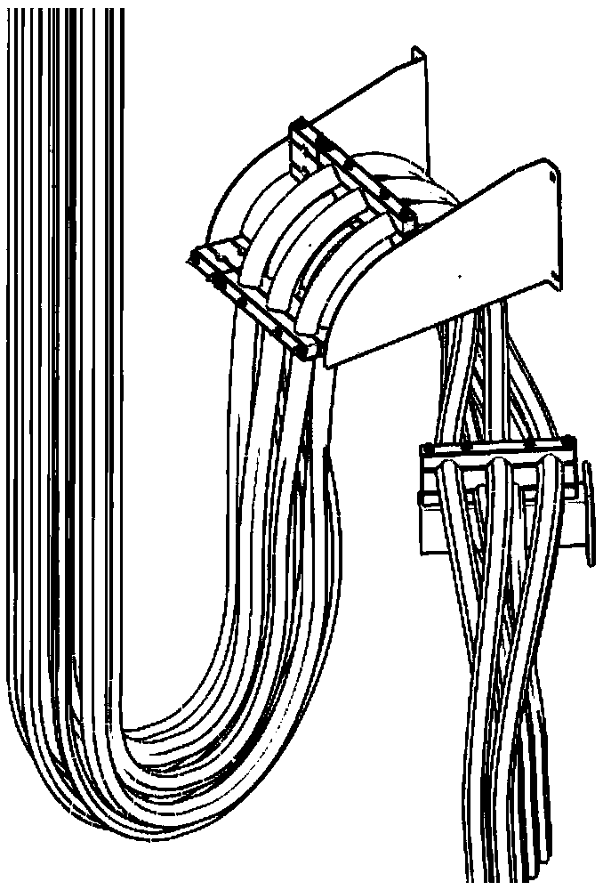
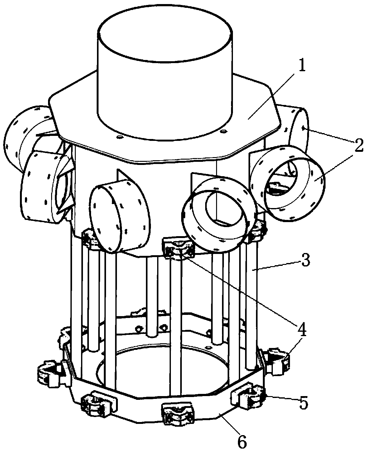
[0020] Such as Figure 2 to Figure 8 As shown, the wind turbine twisted cable saddle device of the present invention includes a central protective tube 1, a saddle hanger 2, a support rod 3, a split cable clamp block 4, a bolt pair 5, and a support seat 6.

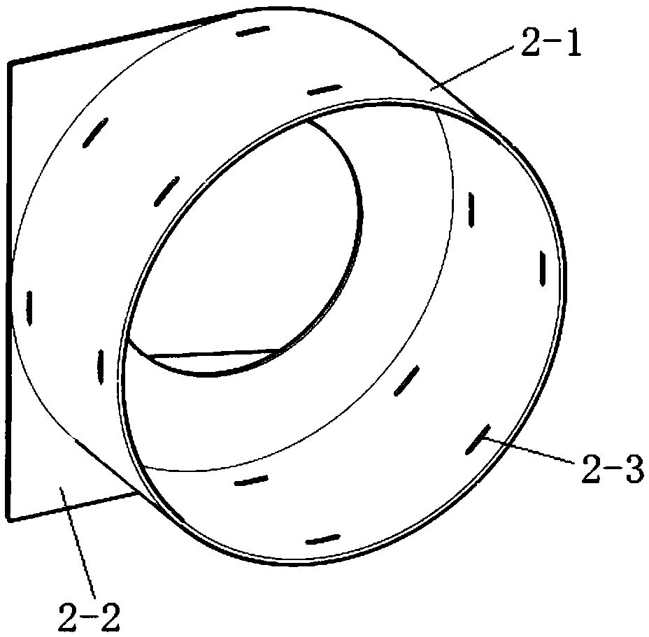
[0021] Eight saddle hangers 2 are welded on the central protective tube 1, and are distributed along the 360° of the lower outer wall of the central protective tube 1 (see figure 2 , 4, 7). The upper ends of eight support rods 3 are welded to the lower end of the central protective tube 1, and are evenly distributed in 360° (see figure 2 ), eight support rods 3 lower ends are welded on the support seat 6. The side of the central protective tube 1 and the side of the support seat 6 correspond to the 3 positions of each support rod and are fixedly connected with a split cable clamp 4 through the ...


PUM


Abstract

The invention relates to a draught fan twisted cable saddle device. The draught fan twisted cable saddle device comprises a central protective cylinder, a plurality of saddle hangers, a plurality of supporting rods, split type cable clamping blocks, bolt pairs and a supporting seat. The saddle hangers are welded to the central protective cylinder and are uniformly distributed along the outer wallof the lower portion of the central protective cylinder at 360 degrees; the upper ends of the supporting rods corresponding to the saddle hangers are welded to the lower end of the central protectivecylinder, and the supporting rods are uniformly distributed at 360 degrees; and the lower ends of the supporting rods are welded to the supporting seat. The side surface of the central protective cylinder and the side surface of the supporting seat are separately fixedly connected with the split type cable clamping blocks at the supporting rods through the bolt pairs. The draught fan twisted cablesaddle device can solve the problems of abrasion between twisted cables and twisted cables, excessive stress on the local twisted cables and the like.

Description

technical field [0001] The invention relates to a wind power generator, in particular to an electrical wiring device of the wind power generator. Background technique [0002] At present, similar products of electrical wiring devices for wind turbines usually use such as figure 1 structure shown. The structure utilizes an integral cable splint to gather multiple groups of "pin"-shaped twisted cables into bundles and then lay them in the form of a falling water bend. When the twisted cable system of the fan is twisted, adjacent groups of "pin"-shaped twisted cables will rub against each other. Risk of abrasion between cables. At the same time, due to the large overall diameter of the cable bundle, there is a large difference in the length of the inner and outer cables of the integral falling water bend. After the structure of the falling water bend is reversed, the inner cables will be tight and the outer cables will be loose, causing excessive local cable load. , leading ...

Claims


Application Information

Patent Timeline
Patent Type & Authority Applications(China)
IPC IPC(8): F03D80/80
CPCF03D80/85Y02E10/72
Inventor 曹勇韦瀚朱清吴梦华陈康龙
Owner YUANJIAN WIND POWER JIANGYINENVISION ENERGY CO LTD
Why Eureka
Try Eureka