Tunneling and bolt supporting device

A technology of equipment and roadheader, which is applied in mining equipment, bolt installation, earthwork drilling and mining, etc. It can solve the problems of not being able to install roof bolts, restricting the installation position of bolting machines, limiting the number of bolting machines and operating range, etc. Achieve the effects of improving construction speed and labor production efficiency, preventing roof separation and sinking, and eliminating the phenomenon of waiting for idle work

Pending Publication Date: 2018-12-14
日照市上普重型装备股份有限公司
View PDF7 Cites 5 Cited by
  • Summary
  • Abstract
  • Description
  • Claims
  • Application Information

AI Technical Summary

Problems solved by technology

[0003] In order to improve labor efficiency and reduce the labor intensity of construction workers, some mining companies use hydraulic bolter rigs to complete the remaining bolts ( Anchor cable) support workload, but this operation method is limited by the span of the construction roadway (generally about 3.5-5.5m), and because of the impact of the space occupied by the material transfer conveyor or the external conveyor, the hydraulic rock bolt drill The effective operating space of the truck is very limited, which significantly reduces the construction efficiency of the hydraulic rock bolter, and also seriously affects the passage of construction workers and the handling of supporting materials.
[0004] In order to solve the problem that the cutting and material loading speed of the existing cantilever horizontal axis bolter integrated machine is fast, the bolt support speed is low, the support speed cannot keep up with the cutting and material loading speed, and the support speed seriously restricts the construction speed. Problem, the Chinese invention patent with the publication number CN102704929B discloses a technology of installing a side bolter on the supporting trolley of the transfer conveyor at the rear of the cantilever type horizontal axis bolter. On the one hand, the side bolter It is only installed on the supporting trolley of the transfer conveyor, so that the installation position of the bolter is strictly limited, which greatly limits the number of installations and the scope of work of the bolter, and affects the further improvement of the construction speed. On the other hand, if the matching The distance between the trolley and the roadheader is relatively large (generally greater than 10m), resulting in a section of roadway behind the roadheader that cannot be supported in time and effectively, which may cause the roadway to collapse and the roof to sink from the layer, which is not conducive to the long-term stability of the roof, and may even Therefore, a roof fall accident is caused. If the distance between the supporting trolley and the roadheader is close, the materials unloaded from the transfer conveyor can only be transported by a rubber-tyred shuttle car. However, there are many problems in this transportation method, otherwise it will inevitably be due to the transfer of materials. The tail of the external belt conveyor overlapped by the conveyor frequently moves forward, which affects production; in addition, the bolter installed on the supporting trolley is only a side bolter, which can only construct the side bolts of the roadway, and cannot construct the roof anchor of the roadway Rods and anchor cables are far from maximizing the effect of increasing construction speed
[0005] To sum up, the known technologies for bolt (cable) supplementary support operations at the back of the roadheader all have deficiencies, and it is very necessary to improve them

Method used


Image

  • Tunneling and bolt supporting device
  • Tunneling and bolt supporting device
  • Tunneling and bolt supporting device

Examples


Embodiment Construction

[0022] The technical solution of the present invention will be described in detail below in conjunction with the accompanying drawings and specific embodiments to further understand the purpose, solution and effect of the present invention, but it is not intended to limit the scope of protection of the appended claims of the present invention.

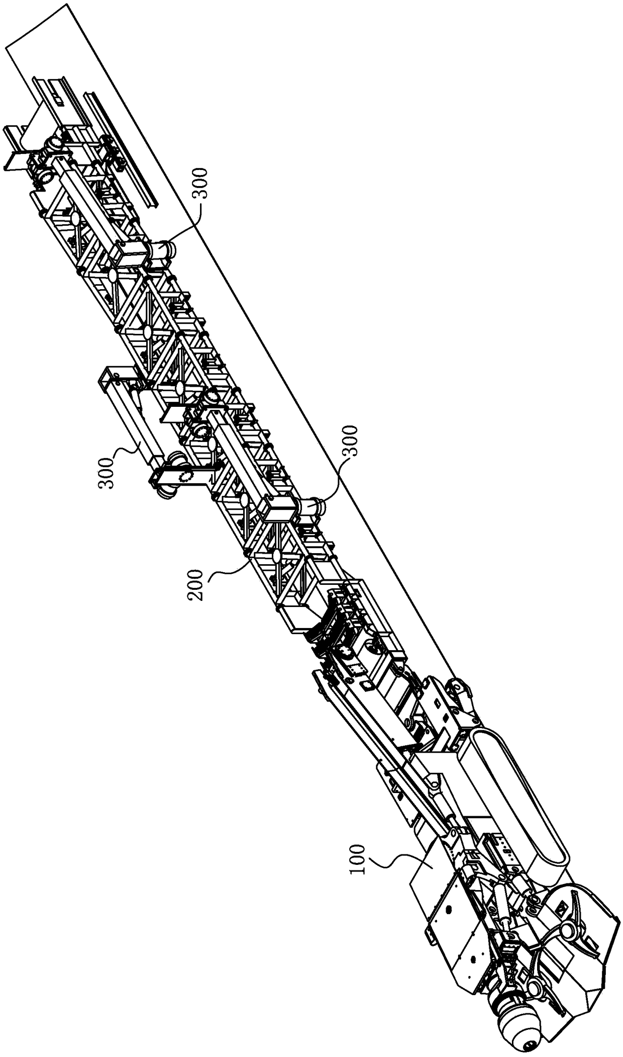
[0023] Such as figure 1 As shown, a kind of bolt digging equipment includes a roadheader 100, a material transfer conveyor 200 and a bolt support device 300. The roadheader 100 is provided with a chassis and a cantilever cutting part, and the chassis includes a frame body and double crawlers The frame body is connected to the double-crawler walking part; the material transfer conveyor 200 is arranged behind the roadheader 100 and is movably connected with the roadheader 100, and the material transfer conveyor 200 is commonly called the second conveyor. As we all know, the cantilever cutting part refers to the cutting part of the roadhe...


PUM


Abstract

The invention discloses a tunneling and bolt supporting device. A bolt supporting device comprises a first turning device, a vertical swing drill arm and a first hydraulic telescopic cylinder, whereinthe first turning device is disposed on a material transfer conveyor through a mounting base, a first end of the vertical swing drill arm is hinged with a hinge support seat disposed on the first turning device, a second end of the vertical swing drill arm is connected with a drilling frame through a second turning device and a third turning device that are rotationally connected with each other.The tunneling and bolt supporting device is advantaged in that the bolt supporting device and the horizontal turning center of a cantilever type longitudinal axis cutting portion can be matched witha tunneling machine which slides laterally with respect to a chassis, or can be matched with a cantilever type horizontal axis tunneling machine, the advantage of no movement in the cutting process ofthe tunneling machine is fully utilized, parallel operation between rear supporting of the tunneling machine and cutting of the tunneling machine is achieved, an idling phenomenon of waiting of supporting workers in the cutting process of the tunneling machine is eliminated, and construction efficiency can be greatly improved.

Description

technical field [0001] The invention relates to the technical field of roadheaders, in particular to construction equipment integrating the functions of roadheading and bolt support. Background technique [0002] In order to improve the construction speed of the cantilever longitudinal axis roadheader, the usual bolt support method is to complete the key bolt (cable) support in front of the chassis of the roadheader, and the rest of the bolt (cable) support workload, It is completed with a hand-held pneumatic single-body bolter behind the roadheader. [0003] In order to improve labor efficiency and reduce the labor intensity of construction workers, some mining companies use hydraulic bolter rigs to complete the remaining bolts ( Anchor cable) support workload, but this operation method is limited by the span of the construction roadway (generally about 3.5-5.5m), and because of the impact of the space occupied by the material transfer conveyor or the external conveyor, th...

Claims


Application Information

Patent Timeline
Patent Type & Authority Applications(China)
IPC IPC(8): E21D9/10E21D20/00
CPCE21D9/10E21D20/003
Inventor 曲天智
Owner 日照市上普重型装备股份有限公司
Why Eureka
Try Eureka