
Dialysis cartridge

Inactive Publication Date: 2005-05-05
WILSON WOLF MFG
View PDF10 Cites 20 Cited by
  • Summary
  • Abstract
  • Description
  • Claims
  • Application Information

AI Technical Summary

Benefits of technology

[0011] It is an object of the present invention to provide a device that can interface with standard laboratory pipettes for the introduction and removal of samples, integrate a high ratio of dialysis membrane surface area to sample volume size for improved mass transfer, automatically orient in a beneficial position when residing in dialysate solution, and prevent the potential for damage to the dialysis membrane from osmotic imbalance between the sample and the dialysate.
[0012] In one embodiment, the need for a gasket as a seal is eliminated, thereby creating an excellent surface area to volume ratio, and allowing access of the dialysis compartment by way of either a laboratory pipette or needle. If a user prefers to use a needle, the needle is oriented in a manner that reduces risk of needle injury to the user, and minimizes risk of needle damage to the dialysis membrane.
[0013] In another embodiment, a gasket is used for a seal, but is configured to allow the use of either a laboratory pipette or a needle in a manner to provide an improved surface area to volume ratio. If a user prefers to use a needle, the needle is oriented in a manner that reduces risk of needle injury to the user, and minimizes risk of needle damage to the dialysis membrane.
[0014] In another embodiment, the device is configured to automatically orient itself into a beneficial position for dialysis while being prevented from sinking to the bottom of the dialysate solution.
[0015] In another embodiment, the device is configured with a grid that protects the membrane from damage.
[0016] In another embodiment, the device controls pressure increases due to osmotic gradients by allowing a portion of the sample to move into a displacement compartment, thereby reducing pressure placed upon the delicate dialysis membranes.

Problems solved by technology

The shortcomings include a poor membrane surface area to sample volume ratio, the need for users to make liquid tight seals, and loss of control over the location of the tubing within the dialysate.
Since dialysis tubing takes the shape of a cylinder when filled with a sample, the inherent geometry leads to a poor rate of mass transfer.
This leads to delayed sample dialysis time.
Another drawback of using dialysis tubing is related to its method of fabrication.
The fact that the tubing is flimsy, particularly when wet, makes it difficult to perform the sealing operation.
Loss of sample can occur during this step from spillage, or leaking if the seal is not liquid tight.
If the tube sinks to the bottom of the container, it can be hit by the spinning stir bar and break open, resulting in loss of the valuable sample.
Unfortunately, a great deal of manufacturing complexity is added to achieve this objective.
Most importantly, no improvement to the poor surface area to volume ratio is made.
However, the improvements come at the cost of eliminating the ability to use standard laboratory pipettes as a tool to access the sample compartment.
Needles must be used, and in a manner that increases the possibility of a needle puncture to the operator and needle damage to the dialysis membranes.
Even if the needle does not slip out of place and render injury to the user, it can easily damage the dialysis membrane.
Even a slight deviation from parallel as the needle emerges from the gasket can cause the needle to puncture the very thin dialysis membrane.
This problem is compounded because the needle has a tendency to accelerate as it exits the gasket due to the substantial reduction in resistance at that point, making it hard to control the needle.
When removing a sample, the dialysis membrane is wet and has a tendency to sag, orienting it directly in the path of needle travel.
Since the samples being dialyzed can be very expensive, and loss to puncture of the dialysis membrane is quite possible, this design flaw is a very detrimental characteristic of the apparatus.
Another problem with the requirement of inserting a needle through a gasket to deliver and remove the sample is that it limits any further reduction in surface area to volume ratio because the gasket must be of a minimum thickness so that a needle can penetrate it.
Therefore, reducing the thickness of the dialysis cartridge is limited by the needle diameter.
Another drawback is that there is no provision for preventing the device from sinking in the dialysate and potentially making contact with a spinner bar.
Yet another drawback, which is also present in dialysis tubing, is the potential loss of a sample due to osmotically driven water flux.
Since the membranes allow fastest mass transfer when they are very thin, sometimes no more that 0.0003 inches thick, they are inherently weak.
Unfortunately, this reduces the advantage of mass transfer speed obtained by the improved surface area to volume ratio.
However, a major drawback is the poor surface area to sample volume that results, limiting the speed of mass transfer.
Thus, this disclosure is not helpful in resolving the surface area to volume ratio problems that are inherent to dialysis tubing.
However, there are shortcomings in terms of surface area to volume ratio, the required use of needles, the required orientation of the needle a manner that could cause injury to users or damage to the dialysis membrane, the need to attach secondary components to allow proper orientation in the dialysate solution, and the possibility of membrane damage from osmotic pressure differential.

Method used


Image

  • Dialysis cartridge
  • Dialysis cartridge
  • Dialysis cartridge

Examples


Embodiment Construction

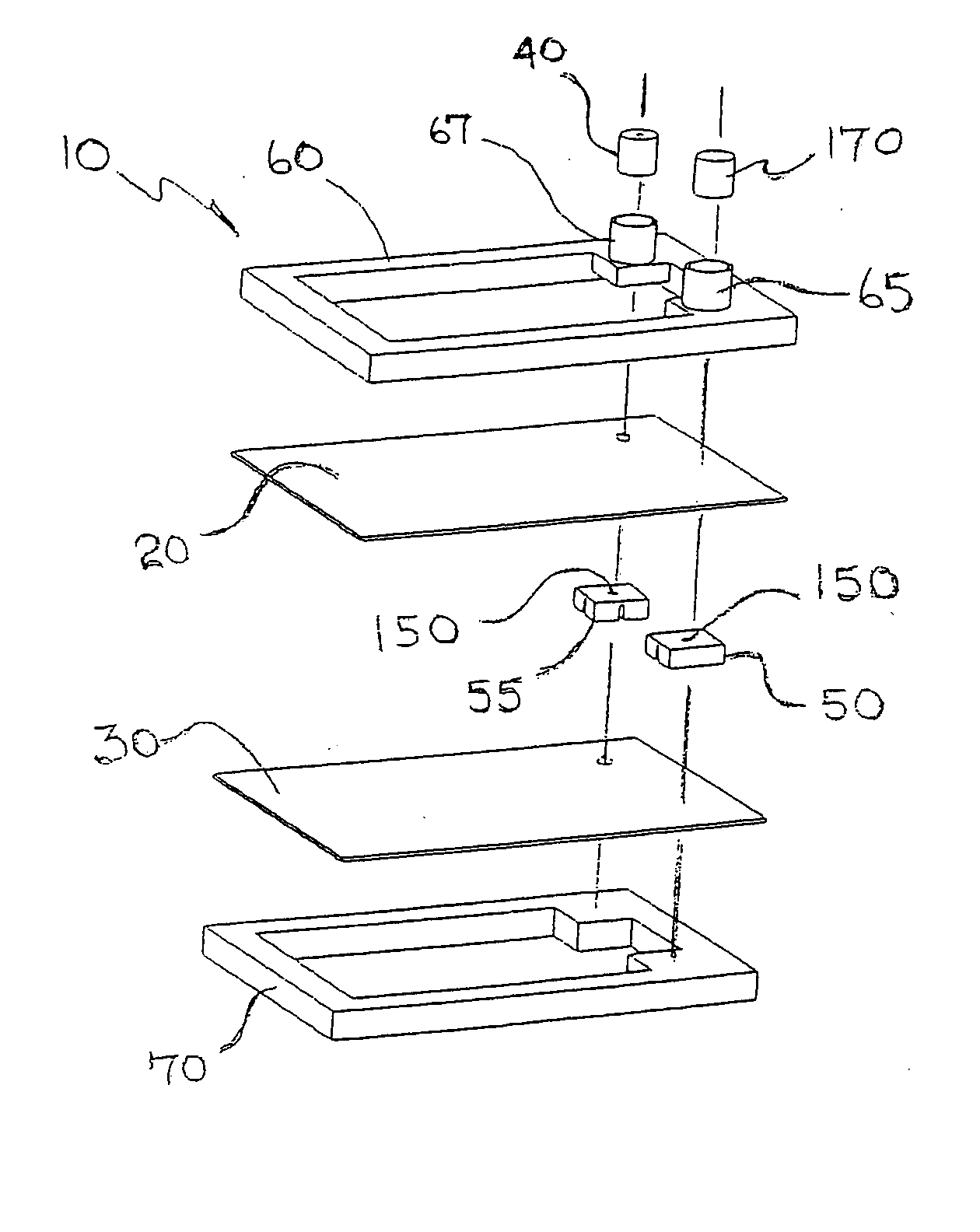
[0029] Exploded views of a preferred embodiment of dialysis cartridge 10 are depicted in FIG. 1A from an upper perspective, and FIG. 1B from a lower perspective. Needle access disk 50 and pipette access disk 55 reside between upper membrane 20 and lower membrane 30. Upper frame 60 and lower frame 70 sandwich upper membrane 20 and lower membrane 30 together about their perimeters, and at the upper surfaces of needle access disk 50 and pipette access disk 55, making a liquid tight compartment for sample. Perimeter sealing ridge 62, emanating from upper frame 60, presses against lower frame 70 in order to create a liquid tight seal about the perimeter of upper membrane 20 and lower membrane 30. Upper frame 60 contains needle access port holder 65, pipette access port holder 67, each with fluid transport opening sealing ridges 63, best shown in FIG. 1C which is Detail A of FIG. 1B. Fluid transport opening sealing ridges 63 apply the appropriate force against needle access disk 50 and pi...


PUM

PropertyMeasurementUnit
Pressureaaaaaaaaaa
Sizeaaaaaaaaaa
Surface areaaaaaaaaaaa

Abstract

An easy to use device for the dialysis of a sample. The device embodies a liquid tight compartment, a portion of which is a membrane capable of allowing molecules and compounds of a pre-determined size to pass into and out of the compartment. The cartridge can be fabricated in a manner that provides a highly efficient surface area to volume ratio between the membrane and the sample, allows the use of standard laboratory pipettes for sample introduction and removal, is automatically oriented in a beneficial position when residing in dialysate solution, and prevents the potential for damage to the membrane from osmotic imbalance between the sample and the dialysate.

Description

RELATED APPLICATION [0001] The present application claims the benefit of U.S. Provisional Application No. 60 / 517,208 filed Nov. 4, 2003, which is incorporated herein in its entirety by reference.FIELD OF THE INVENTION [0002] The present invention relates to a device for the dialysis of small samples such as those commonly dialyzed in research laboratories. The device can interface with standard laboratory pipettes for the introduction and removal of samples, integrate a high ratio of dialysis membrane surface area to sample volume size for improved mass transfer, automatically orient in a beneficial position when residing in dialysate solution, and prevent the potential for damage to the dialysis membrane from osmotic imbalance between the sample and the dialysate. BACKGROUND [0003] Dialysis of samples to alter the molecular composition is a routine laboratory practice. Placing the sample in a container that is comprised of a dialysis membrane, and immersing the container in a dialy...

Claims


Application Information

Patent Timeline
IPC IPC(8): B01D61/28B01D63/08B01L3/00G01N1/34
CPCB01D61/28B01D63/082B01L3/502715B01L2200/027B01D2315/06B01L2300/0681B01L2300/0816G01N1/34G01N2001/4016B01L2200/085B01D63/0822
Inventor WILSON, JOHN R.
Owner WILSON WOLF MFG
Learn More