
Combination umbrella and folding chair and associated method

a technology of umbrellas and folding chairs, applied in the field of umbrellas, can solve the problems of not including cups and means, not providing umbrellas and beach chairs in one convenient assembly,

Inactive Publication Date: 2009-07-21
RONDEAU AMANDA J
View PDF6 Cites 20 Cited by
  • Summary
  • Abstract
  • Description
  • Claims
  • Application Information

AI Technical Summary

Benefits of technology

[0019]The assembly further includes a mechanism for storing and transporting the umbrella section and the chair section simultaneously. Such a storing and transporting mechanism is effectively detachable from the umbrella section and the chair section respectively during operating conditions. The storing and transporting mechanism includes a deformably resilient and flexible bag with an open top end. Such an open top end allows the apparatus to be introduced into an interior of the bag, and the bag conveniently is suitably shaped and sized such that the apparatus is surrounded by the bag when the apparatus is introduced into the interior thereof during storage and transport procedures respectively. The second pole is abutted directly against the first pole along the respective longitudinal lengths thereof and the chair section is in the collapsed position prior to introducing the apparatus into the interior of the bag.
[0023]The method further includes the steps of: hingedly attaching a top end of a first rectilinear pole directly to a bottom end of a second rectilinear pole and locking the bottom end of the second pole into the top end of the first pole when the top end of the second pole is biased upwardly and away from the top end of the first pole. Such a second pole is biased 180 degrees along an arcuate path defined about the hinged attachment point. The steps further include attaching a rotatable knob directly and simultaneously to the top end of the first pole and the bottom end of the second pole. Such a knob allows the user to maintain the second pole in a fixed position at a multitude of discrete points along the arcuate path.
[0026]The steps further include providing first and second crossed support members pivotally attached to each other at respective medial portions thereof. Each of such first and second cross members have equal longitudinal lengths respectively, and each of the first and second cross members further have axially opposed top and bottom ends respectively. The steps further include providing a flexible and planar seat member with axially opposed corners simultaneously connected to the first pole of the umbrella section and the first, second, and third vertical support members respectively such that the seat member spans therebetween during operating conditions. Such a seat member has a top surface in contact with the user body when the user is seated thereupon, and such a top surface is maintained along a horizontal plane during operating conditions. The seat member further includes a bottom portion in contact with a ground surface, which is provided for preventing the assembly from sinking into the ground surface when the invention is utilized at a beach setting. Such a bottom portion further helps keep the assembly afloat when positioned in body of water.
[0031]The method further includes the steps of: providing a deformably resilient and flexible bag with an open top end and introducing the apparatus through the open top end of the bag and into an interior of the bag. Such a bag is suitably shaped and sized such that the apparatus is surrounded by the bag when the apparatus is introduced into the interior thereof during storage and transport procedures respectively. The steps further include attaching a slidable drawstring to an outside surface of the open top end of the bag. Such a drawstring maintains the open top end in a closed position when the apparatus is introduced into the interior of the bag such that the apparatus is prohibited from prematurely and undesirably exiting the interior of the bag during storage and transport procedures respectively.

Problems solved by technology

Unfortunately, this prior art example does not include a cup holder and a means for folding the entire assembly into a single transportable container.
Unfortunately, this prior art example does not provide an umbrella and beach chair in one convenient assembly.

Method used


Image

  • Combination umbrella and folding chair and associated method
  • Combination umbrella and folding chair and associated method
  • Combination umbrella and folding chair and associated method

Examples


Embodiment Construction

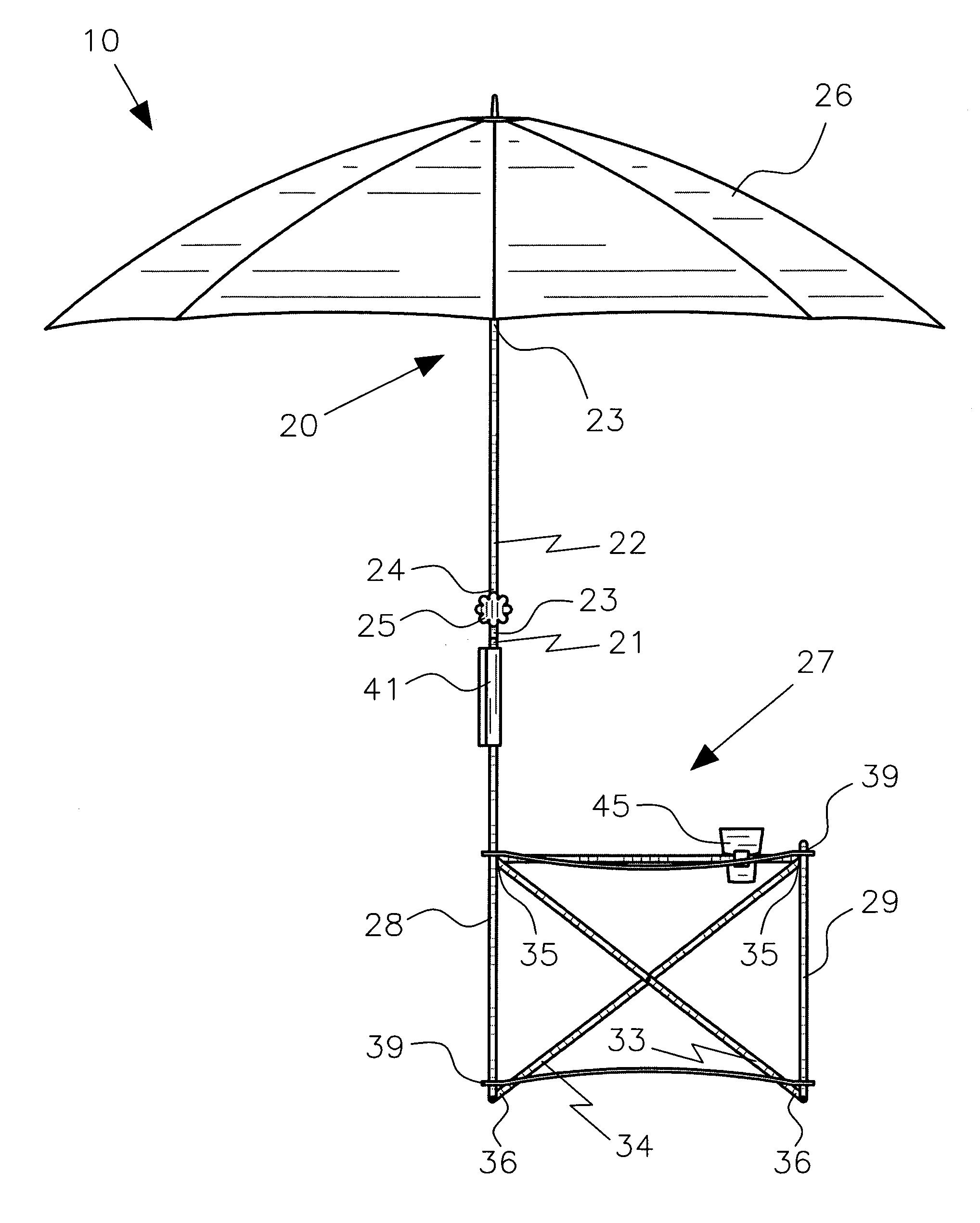
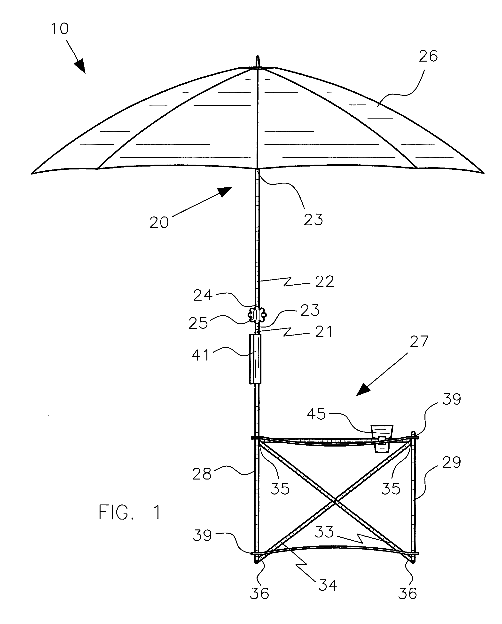
[0044]The present invention will now be described more fully hereinafter with reference to the accompanying drawings, in which a preferred embodiment of the invention is shown. This invention may, however, be embodied in many different forms and should not be construed as limited to the embodiment set forth herein. Rather, this embodiment is provided so that this application will be thorough and complete, and will fully convey the true scope of the invention to those skilled in the art. Like numbers refer to like elements throughout the figures.

[0045]The assembly of this invention is referred to generally in FIGS. 1-8 by the reference numeral 10 and is intended to provide a means for providing a barrier between a user and the sun or rain while the user employs the chair in outdoor environments. It should be understood that the assembly 10 may be used for many different types of outdoor activities and should not be limited in use to only those outdoor activities mentioned herein.

[004...


PUM


Abstract

The combination umbrella and folding chair includes an umbrella section with first and second rectilinear poles with axially opposed top and bottom ends respectively. The umbrella section further includes a rotatable knob that allows the user to maintain the second pole in a fixed position and a circular and flexible covering. The assembly further includes a chair section with a flexible and planar seat member, a flexible and planar backrest, and a ring-shaped cup holder. The assembly further includes a mechanism for storing and transporting the umbrella section and the chair section simultaneously.

Description

CROSS REFERENCE TO RELATED APPLICATIONS[0001]Not Applicable.STATEMENT REGARDING FEDERALLY SPONSORED RESEARCH OR DEVELOPMENT[0002]Not Applicable.REFERENCE TO A MICROFICHE APPENDIX[0003]Not Applicable.BACKGROUND OF THE INVENTION[0004]1. Technical Field[0005]This invention relates to umbrellas and, more particularly, to a combination umbrella and folding chair for providing a barrier between a user and the sun or rain while the user employs the chair in outdoor environments.[0006]2. Prior Art[0007]Beach chairs provide temporary places for people to sit and rest when they are camping, fishing or playing on a beach. To prevent sunburns and receiving excessive rays from the sun, most beach chairs are equipped with a sunshade. A conventional foldable beach chair includes a seat, a backrest, legs, armrests and a sunshade. The backrest usually includes a U-shaped tubular frame with a horizontal top and two essentially vertical sides. The sunshade has a shaft and a securing device that clamps...

Claims


Application Information

Patent Timeline
IPC IPC(8): A47C29/00A47C4/28A47C7/62
CPCA47C7/66A47C4/286
Inventor RONDEAU, AMANDA J.
Owner RONDEAU AMANDA J
Learn More