Separating structure
A separation structure, one-to-one correspondence technology, applied in the direction of conveyor objects, transportation and packaging, etc., can solve the problems of low product yield and inability to separate two parts
- Summary
- Abstract
- Description
- Claims
- Application Information
AI Technical Summary
Problems solved by technology
Method used
Image


Examples
Embodiment 1
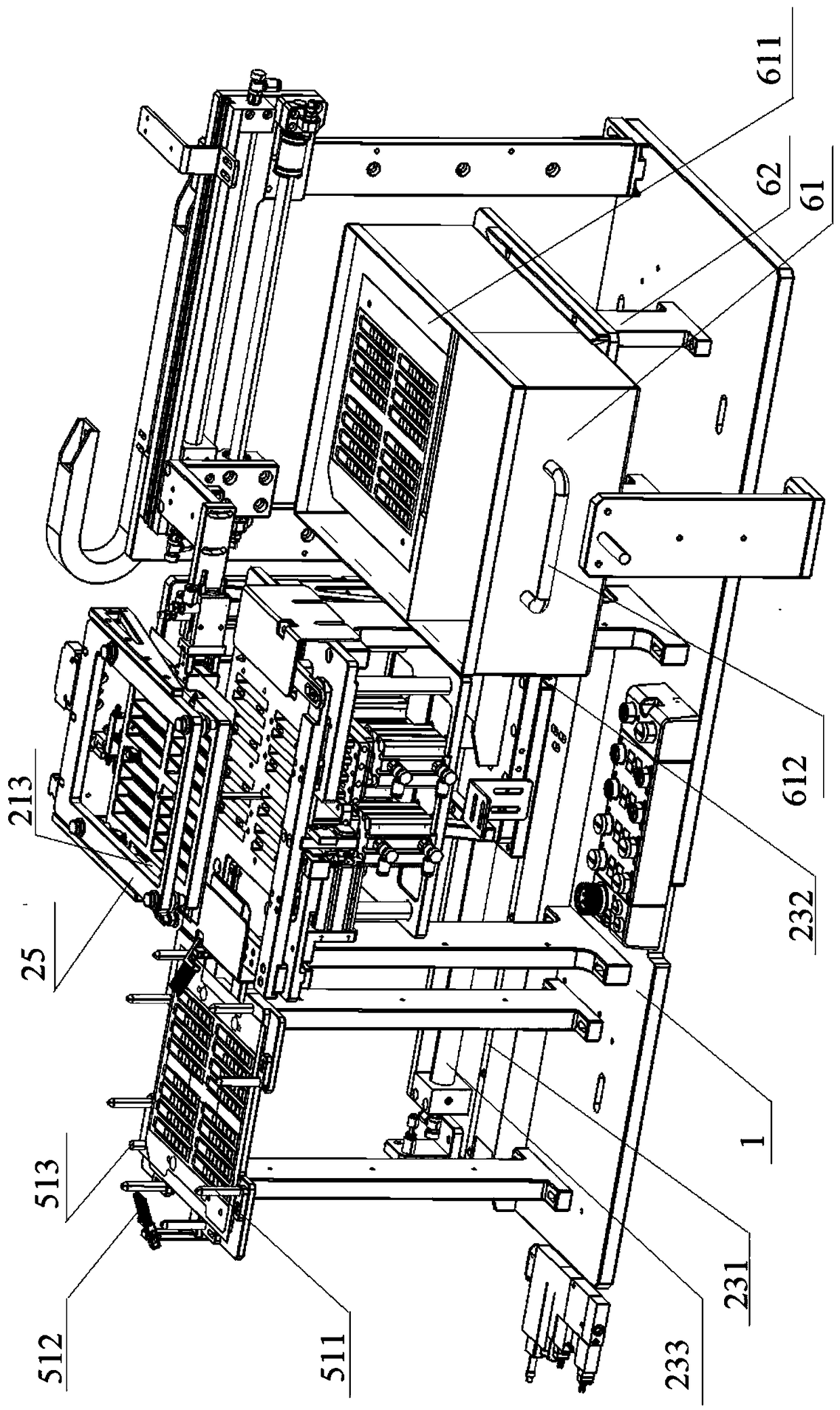
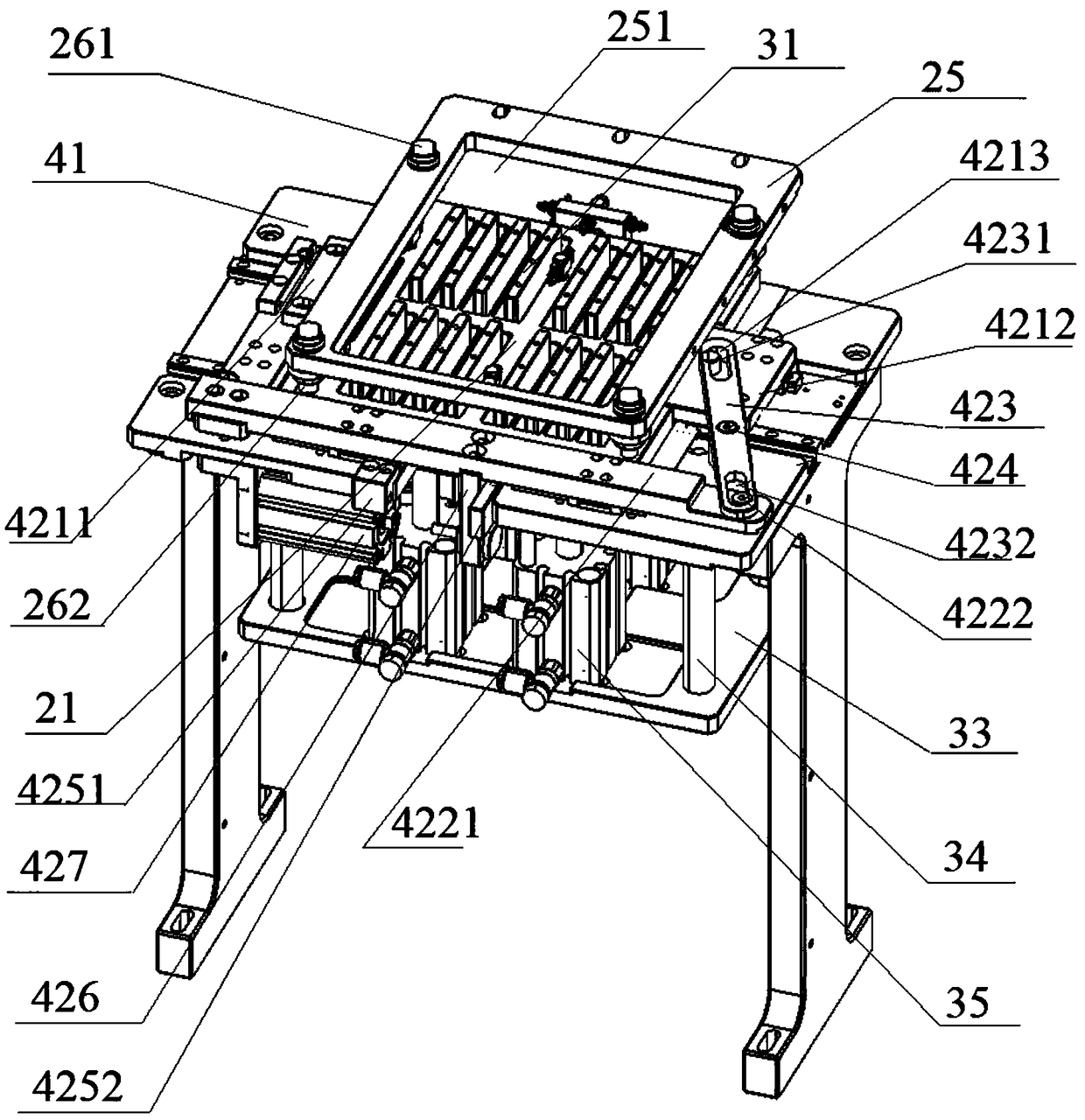
[0087] This embodiment provides a separation structure, such as Figure 1 to Figure 8 As shown, it includes: a base frame 1 , a cutter 31 , a first carrier 21 , a second carrier 41 , a third carrier 51 and a receiving mechanism 6 .
[0088] Wherein, the first stage 21 is slidably arranged relative to the base frame 1 along the first direction, and the workpiece can be adsorbed and mounted on the bottom side of the first stage 21; the second stage 41 is arranged on the base frame 1, and When the first carrier 21 slides horizontally, it can be stacked on the top side of the second carrier 41; It has a separation action state that penetrates the first carrier 21 and the second carrier 41, and separates the parts to be separated of the workpiece from its first through hole; the third carrier 51 is fixedly arranged on the base frame 1, and The second carrier 41 is horizontally staggered; when the first carrier 21 slides, the third carrier 51 can be stacked under the first carrier 21...
Embodiment 2
[0137] This embodiment provides a separation structure, which differs from the separation structure provided in Embodiment 1 in that,
[0138] As the deformation of the number of the second suction hole 311, the second suction hole 311 can also be provided with one, two, four or even more second suction holes 311, as long as the suction effect of the cutter 31 on the parts to be separated is guaranteed That's it.
[0139] As a modification of the number of the first air intake holes 312, the first air intake holes 312 can also be set corresponding to the number of the second air intake holes 311, as long as the negative pressure generated by the second negative pressure assembly is guaranteed to be transmitted to the second air intake The hole 311 is enough.
[0140] As a further modification, the first air inlet 312 may not be provided, as long as the gas pipeline of the second negative pressure assembly is directly communicated with the second air suction hole 311, and nega...
Embodiment 3
[0143] This embodiment provides a separation structure, which differs from the separation structure provided in Embodiment 1 or Embodiment 2 in that:
[0144] As a modification of the rotating part 423, the second long waist hole 4232 may not be provided on the rotating part 423, and the other end opposite to the first long waist hole 4231 is the movable end, and the moving part 4221 can slide against the movable end, For example, by arranging two inclined surfaces correspondingly, the function of the toggle rotating member 423 moving in the second direction can also be satisfied when the toggle member 4221 slides in the first direction.
[0145] As a further deformation of the rotating part 423, the first long waist hole 4231 and the second long waist hole 4232 do not need to be provided on the rotating part 423, and only the outer wall surfaces of the moving part 4221 and the rotating part 423 abut against each other are used to toggle. The position of one end of the rotatin...
PUM
 Abstract
Description
Claims
Application Information
 - Generate Ideas
- Intellectual Property
- Life Sciences
- Materials
- Tech Scout
- Unparalleled Data Quality
- Higher Quality Content
- 60% Fewer Hallucinations
Browse by: Latest US Patents, China's latest patents, Technical Efficacy Thesaurus, Application Domain, Technology Topic, Popular Technical Reports.
© 2025 PatSnap. All rights reserved.Legal|Privacy policy|Modern Slavery Act Transparency Statement|Sitemap|About US| Contact US: help@patsnap.com