Double-break-point medium voltage magnetic retention relay

A magnetic latching relay, double breakpoint technology, applied in electromagnetic relays, relays, detailed information of electromagnetic relays, etc., can solve the problems of inability to meet the stress requirements of equipment systems, high precision requirements, and inability to break, to improve switching capabilities and Debugibility, increase the diversion area, avoid the effect of easy decay

Inactive Publication Date: 2018-12-11
GUIZHOU SPACE APPLIANCE CO LTD
View PDF12 Cites 1 Cited by
  • Summary
  • Abstract
  • Description
  • Claims
  • Application Information

AI Technical Summary

Problems solved by technology

However, the medium-voltage relays in the prior art mainly rely on the deformation of springs and reeds to adjust the speed and clearance of the breaking load. This structure has the following disadvantages: (1) The elastic force of the spring is affected by the high temperature generated by the contacts when breaking the load It is very large. With the switching of products, the elastic force changes in a wide range in the later stage, and it is easy to appear the phenomenon that it cannot be broken; (2) The adjustment range of the structural parameters is small, and the precision requirements for the processing of parts and product assembly are very high, which is not conducive to the realization of mass production. production; (3) The expansion and contraction of the spring occupies a large contact gap, which is not conducive to realizing the miniaturization of the product and obtaining a higher power-to-volume ratio; (4) The anti-vibration ability of the structure is low, which cannot meet the requirements of the equipment system. environmental stress requirements

Method used


Image

  • Double-break-point medium voltage magnetic retention relay
  • Double-break-point medium voltage magnetic retention relay
  • Double-break-point medium voltage magnetic retention relay

Examples


Embodiment Construction

[0023] The technical solution of the present invention is further described below, but the scope of protection is not limited to the description.

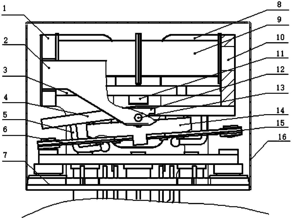
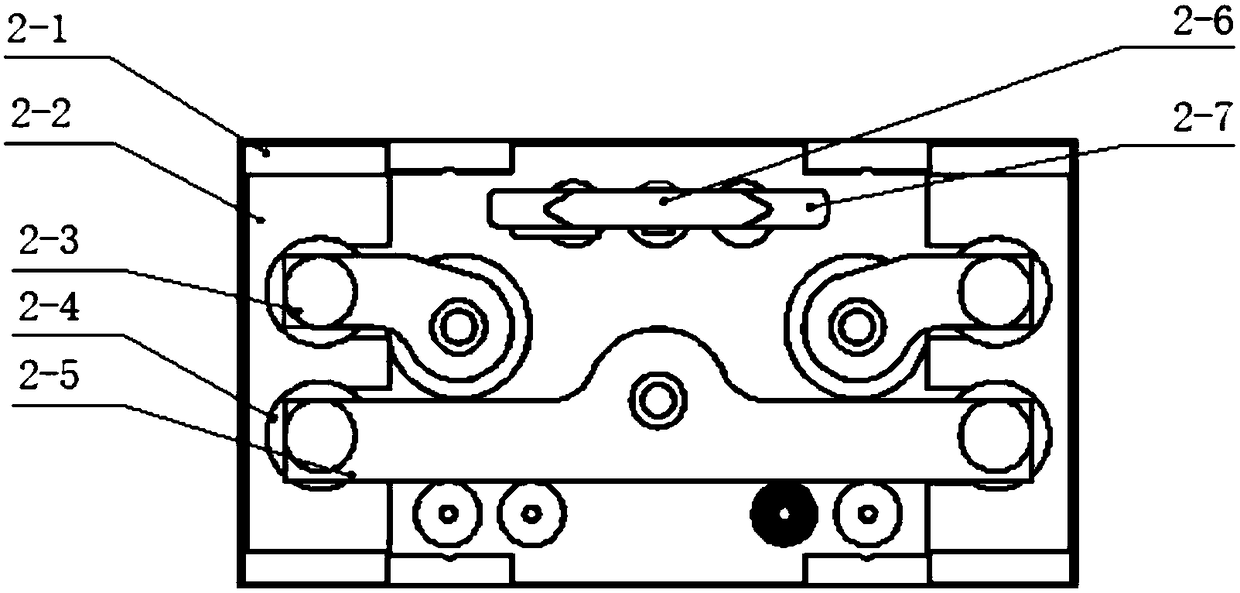
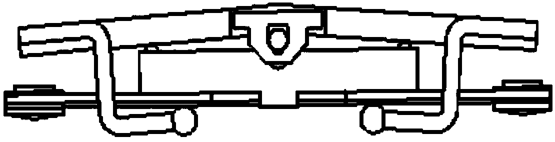
[0024] Such as figure 1 , figure 2 , image 3 and Figure 4 As shown, a double breakpoint medium-voltage magnetic latching relay includes a case 16, and a coil combination, an armature combination and a contact system 7 are arranged in the case 16. The coil combination is located above the armature combination, and the contact system 7 is located below the armature combination. . In addition, the coil assembly can be fixedly connected to the armature assembly through the shaft support piece 2 and the shaft 13 .

[0025] In this embodiment, the coil combination includes a yoke 1, a magnetic steel 3, a coil 9, an iron core 10, and a magnetizer 11. After passing through the coil 9, the iron core 10 is installed on the yoke 1 through a magnet 3, and the magnetizer 11 is installed on the magnet. On the lower end surface of the ste...


PUM


Abstract

The invention relates to a double-break-point medium voltage magnetic retention relay. The relay comprises a cover shell, wherein the cover shell is provided with a coil combination, an armature combination and a contact system, the coil combination comprises a yoke iron, a magnet steel, a coil, an iron core and a magnet conductor, the armature combination comprises an armature and a movable contact piece, the armature is positioned below the magnet steel, movable contacts are arranged at both ends of the movable contact piece, and the movable contacts at both ends of the movable contact piececorrespond to the static contacts of the contact system; The coil is composed of two groups of coils with opposite winding directions. Firstly, one group of coils is energized, and the coil drives the armature to rotate around the shaft and drives the movable contact piece to rotate around the shaft, and is connected with the static contact point on one side of the contact system. The other set of coils is energized, and the coils drive the armature to rotate in the opposite direction about the axis, and drive the movable contact piece to rotate in the opposite direction about the axis, and are connected with the static contact on the other side of the contact system. The invention realizes the breaking contact between the contact system and the movable contact piece, and obtains sufficient clearance for cutting off the load in a limited space.

Description

technical field [0001] The invention relates to a double break point medium voltage magnetic latching relay. Background technique [0002] At present, as the requirements for weapons and equipment increase, the relays used in the equipment system of weapons and equipment are required to have a higher power-to-volume ratio. However, the medium-voltage relays in the prior art mainly rely on the deformation of springs and reeds to adjust the speed and clearance of the breaking load. This structure has the following disadvantages: (1) The elastic force of the spring is affected by the high temperature generated by the contacts when breaking the load It is very large. With the switching of products, the elastic force changes in a wide range in the later stage, and it is easy to appear the phenomenon that it cannot be broken; (2) The adjustment range of the structural parameters is small, and the precision requirements for the processing of parts and product assembly are very high...

Claims


Application Information

Patent Timeline
Patent Type & Authority Applications(China)
IPC IPC(8): H01H50/44H01H50/54H01H51/01
CPCH01H50/44H01H50/54H01H51/01
Inventor 郑太峰马鸿斌
Owner GUIZHOU SPACE APPLIANCE CO LTD
Why Eureka
Try Eureka