
Graphic display system for nuclear power plant safety-level DCS system

A DCS system and graphic display technology, applied to static indicators, instruments, etc., to achieve the effect of flexible interface, simplified interface timing, and complete coprocessor function

Inactive Publication Date: 2018-12-11
CHINA NUCLEAR CONTROL SYST ENG
View PDF5 Cites 5 Cited by
  • Summary
  • Abstract
  • Description
  • Claims
  • Application Information

AI Technical Summary

Problems solved by technology

[0003] The present invention provides a graphic display system for safety-level DCS systems of nuclear power plants, which solves the deficiencies in graphic display control of existing nuclear power plant safety-level DCS systems, realizes flexible system interfaces, complete functions, open source design, and open architecture , the technical effect of hardware design simplification

Method used


Image

  • Graphic display system for nuclear power plant safety-level DCS system
  • Graphic display system for nuclear power plant safety-level DCS system
  • Graphic display system for nuclear power plant safety-level DCS system

Examples


Embodiment 1

[0041] Embodiment 1 overall structure and working mechanism

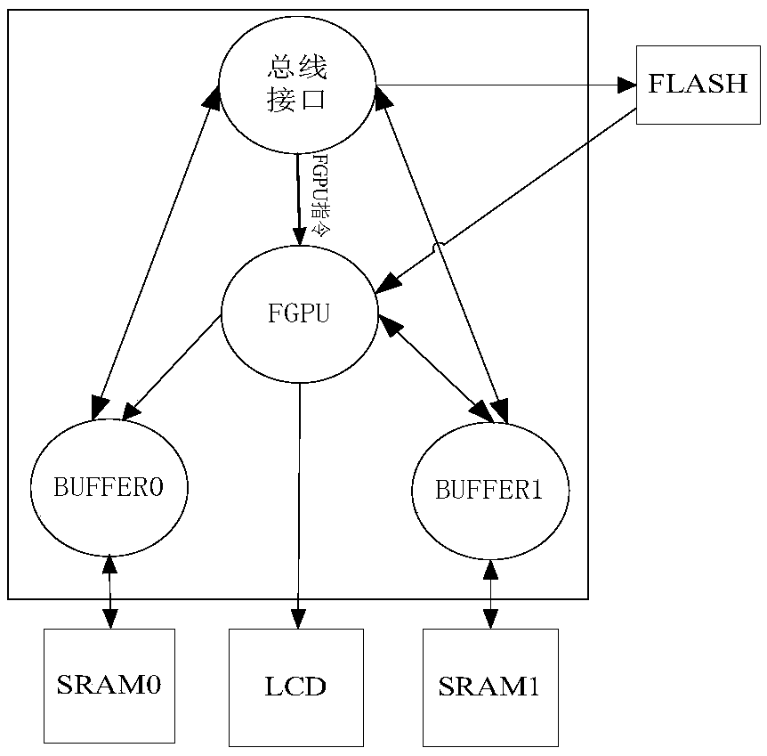
[0042] The overall structure of the system is as figure 1 as shown, figure 1 Among them, SRAM0 and SRAM1 constitute the physical static random access memory corresponding to the double buffer. Flash corresponds to non-volatile static memory. LCD is a 1024X768 pixel liquid crystal display for display. SRAM0, SRAM1, Flash, and LCD are external devices that need to be configured in engineering applications of the present invention.

[0043] figure 1 Among them, the inside of the rectangular frame is the core part of the present invention, and the specific functions are as follows:

[0044] Bus interface: realize the interface with the external processor;

[0045] FGPU: core control scheduling and decoding, LCD display control;

[0046]BUFFER0, BUFFER1: Generate graphic data such as lines and ASCII codes, and perform access control to SRAM0 or SRAM1.

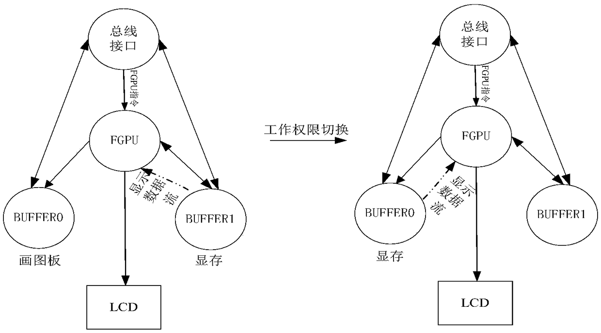
[0047] The working mechanism of the system is:

[0048] fi...

Embodiment 2

[0055] Embodiment 2 bus interface

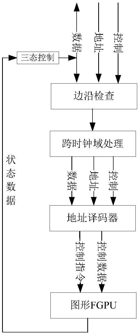
[0056] Such as image 3 , the bus interface completes the following functions:

[0057] Check the edge of the externally input address signal, data signal, and control signal; complete the conversion from the external clock domain to the local clock domain; complete address decoding; tri-state the bidirectional data bus (logic 0, logic 1 and high-impedance )control.

Embodiment 3

[0058] Embodiment 3FGPU function block

[0059] The FGPU function block needs to complete the following two functions: graphics display control state machine; LCD display refresh control.

[0060] Graphical Display Control State Machine

[0061] The functions performed by the graphics display control state machine include: performing secondary decoding on the instructions from the bus interface to determine the graphics display function that should be executed currently. The FGPU instruction set is shown in Table 1, the FGPU parameter set is shown in Table 2, and the FGPU feedback parameter bit function definition is shown in Table 3.

[0062] Table 1 FGPU instruction set

[0063]

[0064] Table 2 FGPU parameter set

[0065]

[0066]

[0067] Table 3 FGPU feedback parameter bit function definition

[0068] bit sequence

Features

Bit 15-12

Reserved, the value is 0

Bit 11

The permissions of BUFFER1. 0: drawing board 1: video memory...


PUM


Abstract

The invention discloses a graphic display system for a nuclear power plant safety-level DCS system. The graphic display system comprises a bus interface, a FGPU functional block, a BUFFER0, and a BUFFER1, wherein the bus interface is used for achieving the interfaces of the system and other external processors; the FGPU functional block is used for sequential control, drawing task scheduling, control instruction state decoding, and LCD display refresh control; and the BUFFER0 and the BUFFER1 are used for generating graphic data, and performing access control on static random access memories SRAM0 and SRAM1. The graphic display system solves the defect of the graphic display control of a conventional nuclear power plant safety-level DCS system, realizes the technical effects of flexible system interface, perfect functions, open-source design, open architecture and simplified hardware design.

Description

technical field [0001] The invention relates to the field of graphic display control, in particular to a graphic display system used in a safety-level DCS system of a nuclear power plant. Background technique [0002] In the safety-level DCS system of nuclear power plants, there are many graphic display devices for operators to monitor the operation of the system. These devices need to meet the friendly human-machine interface display, and also need to comply with relevant laws, regulations, guidelines and standards. Nowadays, more methods of using embedded processor + dedicated graphics display chip are used to realize the graphics display required in the safety-level DCS system of nuclear power plants. This method faces the following problems: it needs to rely on a specific graphics display chip, and the cost is high; the interface is complex; the software corresponding to some functions of the graphics display cannot be V&V; it cannot be flexibly customized to develop sp...

Claims


Application Information

Patent Timeline
Patent Type & Authority Applications(China)
IPC IPC(8): G09G3/36
CPCG09G3/36
Inventor 马权罗琦赵洋马文桂陈达其余波韩文兴刘明星王远兵刘艳阳宋小明
Owner CHINA NUCLEAR CONTROL SYST ENG
Learn More