Eureka AIR delivers breakthrough ideas for toughest innovation challenges, trusted by R&D personnel around the world.

LED light-emitting board without dark side

A technology of light-emitting panels and LED strips, applied in light guides of lighting systems, semiconductor devices of light-emitting elements, optics, etc., can solve the problems of being unable to be illuminated, unsatisfied, and unable to be used normally, so as to increase the difficulty of transportation and transport Effects of cost, increased installation space, and increased packaging volume

Inactive Publication Date: 2018-12-11
朴明灿
View PDF0 Cites 0 Cited by
  • Summary
  • Abstract
  • Description
  • Claims
  • Application Information

AI Technical Summary

Problems solved by technology

With the continuous development of the industry, many high-end users have higher and higher requirements for LED light-emitting panels. The existing LED light-emitting panels can no longer meet the requirements of many high-quality customers, and further improvement is urgently needed.
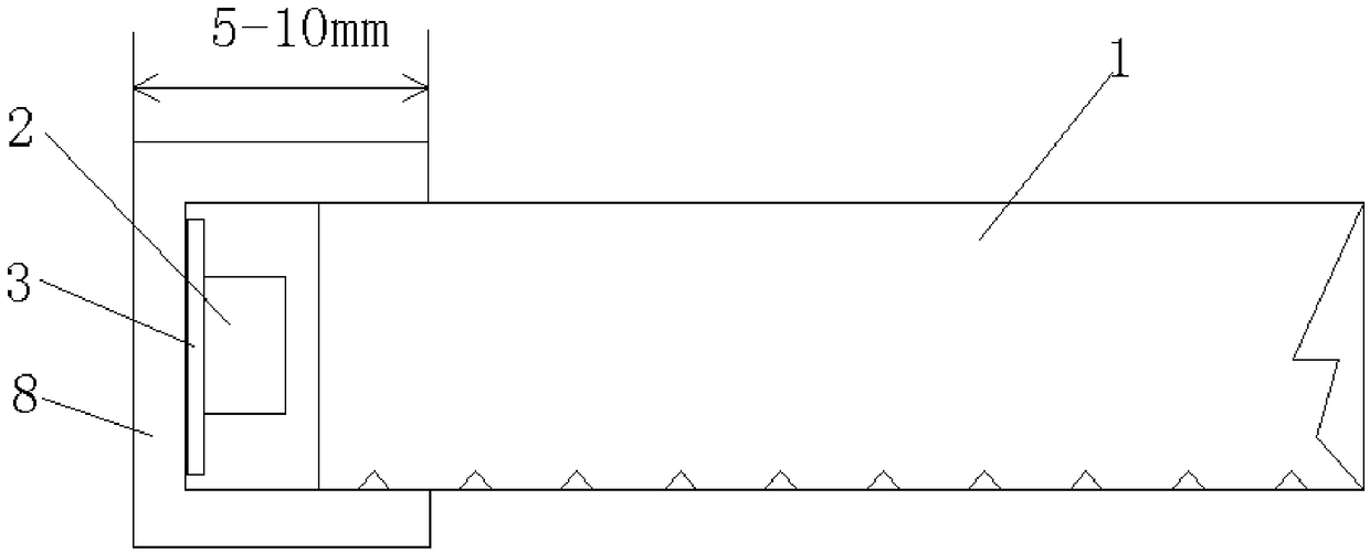
[0003] The existing LED light-emitting panels mainly have two structures, the traditional method A: refer to figure 1 As shown, the LED light bar 3 is installed on one side of the acrylic light-emitting board body 1, and the LED light bar 3 is fixed with an aluminum alloy fixing frame 8 with a groove. The aluminum alloy fixing frame 8 is 5-10mm wide. Therefore, the entire The 5-10mm of the edge of the light-emitting board will be affected by the aluminum alloy fixed frame, which cannot be illuminated and forms a dark frame. When installing, it is necessary to increase the installation space by 5-10mm
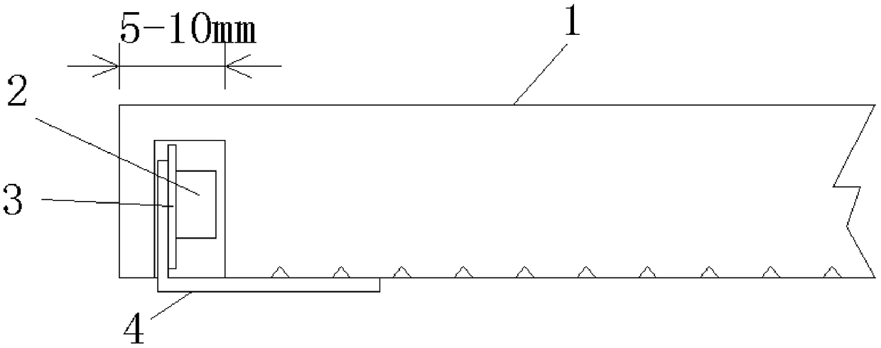
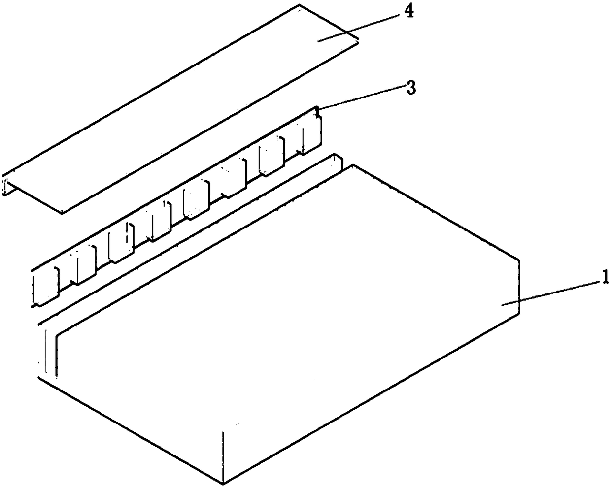
[0004] Traditional way B: such as figure 2 As shown in -4, set a light groove on one side of the acrylic light-emitting board body 1, fix the LED light bar 3 in the light groove, and then install an L-shaped aluminum connecting plate 4 between the LED light bar and the edge of the acrylic light-emitting board body , due to the need to set the light groove, the edge of the acrylic light-emitting board body will have a thickness of several millimeters, plus the width of the light groove itself, so the distance between the light-emitting point of the LED light-emitting board and the edge of the LED light-emitting board is 5-10mm. distance, the 5-10mm cannot be illuminated, making the edge of the entire LED light-emitting panel dark
[0005] Therefore, the user has to consider the special treatment of the 5-10mm edge when installing and using, and the final product cannot meet the requirement that the entire product is a light-emitting surface.
[0006] In addition, the connection between the existing LED light-emitting board power cord and the LED light bar is only connected by tin welding without any protective measures. Due to the length and weight of the power cord, the user will accidentally pull it off during use or installation. The connection between the LED light bar and the power cord makes the light-emitting board power off and cannot be used normally

Method used


Image

  • LED light-emitting board without dark side
  • LED light-emitting board without dark side
  • LED light-emitting board without dark side

Examples


Embodiment 1

[0033] refer to Figure 5 As shown in -7, the present invention provides an LED luminous panel without dark edges, which includes a luminous panel body 1 and an LED light bar 3. A notch is provided on one side of the luminous panel body 1, and the notch is located on the backlight surface. , the light-emitting surface forms a boss 5, an LED light strip is installed at the gap of the light-emitting board body 1, LED light beads 2 are installed on the LED light strip 3, an L-shaped aluminum connection plate is installed on the side of the boss 5, and an L-shaped aluminum connecting plate is installed. The connecting plate 4 is fixed to the side of the boss 5 through heat-conducting double-sided adhesive tape, and the back of the L-shaped aluminum connecting plate 4 is fixed to the backlight surface of the luminous panel body 1 .

[0034] Preferably, the LED light bar 3 is pasted on the L-shaped aluminum connecting plate 4 with a heat-conducting adhesive tape.

[0035] The L-sha...

Embodiment 2

[0043] refer to Figure 8 As shown, the power cord installation groove is set on the back of the luminous panel body, the power cord can go out from any position on the back or side of the luminous panel body, the processing size of the power cord installation groove can be processed to the size of the power cord, and then Put in transparent AB glue or transparent hot melt glue, after the power cord is completely solidified in the power cord installation groove, fix the power cord with rivets at the outlet to increase the firmness.

[0044] The light-emitting board body of the present invention can be a rectangular, square, circular or other special-shaped light-emitting board. The back of the light-emitting board body is CNC processed according to the thickness of the LED light bar, and the processing depth is CNC processed according to the width of the LED light bar.


PUM

PropertyMeasurementUnit
Widthaaaaaaaaaa

Abstract

The invention discloses an LED light-emitting board without a dark side. The LED light-emitting board without the dark side comprises a light-emitting board body and an LED light bar; a notch is formed in one side of the light-emitting board body and arranged on the shady face; a boss is arranged on the light-emitting face; the LED light bar is installed at the notch of the light-emitting board body; an L-type aluminum connection board is installed on the side face of the box and fixed to the side face of the boss through heat conduction double-faced adhesive tape; and the back face of the L-type aluminum connection board is fixed to the shady face of the light-emitting board body. According to the LED light-emitting board without the dark side, the whole light-emitting face can emit light, the overall product is more attractive, the use effect is good, and the defect that a power line is prone to being pulled and broken can be overcome.

Description

technical field [0001] The invention relates to the field of LED light-emitting panels, in particular to an LED light-emitting panel without dark edges. Background technique [0002] LED light-emitting board is a common lighting device, which is widely used in various fields such as advertising, decoration, equipment lighting, and living lighting, especially high-end shop decoration or product shelf lighting such as cosmetics, clothing, and jewelry. With the continuous development of the industry, many high-end users have higher and higher requirements for LED light-emitting panels. The existing LED light-emitting panels can no longer meet the requirements of many high-quality customers, and further improvement is urgently needed. [0003] The existing LED light-emitting panels mainly have two structures, the traditional method A: refer to figure 1 As shown, the LED light bar 3 is installed on one side of the acrylic light-emitting board body 1, and the LED light bar 3 is f...

Claims


Application Information

Patent Timeline
IPC IPC(8): F21V8/00F21V19/00F21V29/89G02B6/00F21Y115/10
CPCF21V19/005F21V29/89F21V2200/20F21Y2115/10G02B6/0091
Inventor 朴明灿
Owner 朴明灿
Why Eureka
Eureka Blog
Learn More