
Rail vibration damping fastener

A technology of damping fasteners and rails, which is applied in the field of rail transit, can solve problems such as bulky pressurizing devices, increased maintenance workload and capital investment, and unrealistic problems, so as to simplify installation and maintenance operations, eliminate hidden dangers of driving safety, and improve The effect of structural stability

Pending Publication Date: 2018-12-11
洛阳科博思新材料科技有限公司
View PDF11 Cites 4 Cited by
  • Summary
  • Abstract
  • Description
  • Claims
  • Application Information

AI Technical Summary

Problems solved by technology

However, as the frequency of the above-mentioned problems increases, the workload and capital investment of track maintenance and repair will increase greatly; especially in the rail transit operation lines, the operation work is very busy, and it is unrealistic to stop normal operation work for track maintenance; Rely on short operating intervals for inspection and maintenance; therefore, in actual operation, because the special pressurization device is very bulky and inconvenient to operate, construction workers often use other methods, such as knocking and smashing the positioning block into the position forcibly, causing buckling over time Problems such as damage to parts and components, dimensional deviation, etc., in turn aggravate the development of the problems mentioned in 1, forming a vicious circle

Method used


Image

  • Rail vibration damping fastener
  • Rail vibration damping fastener
  • Rail vibration damping fastener

Examples


Embodiment 1

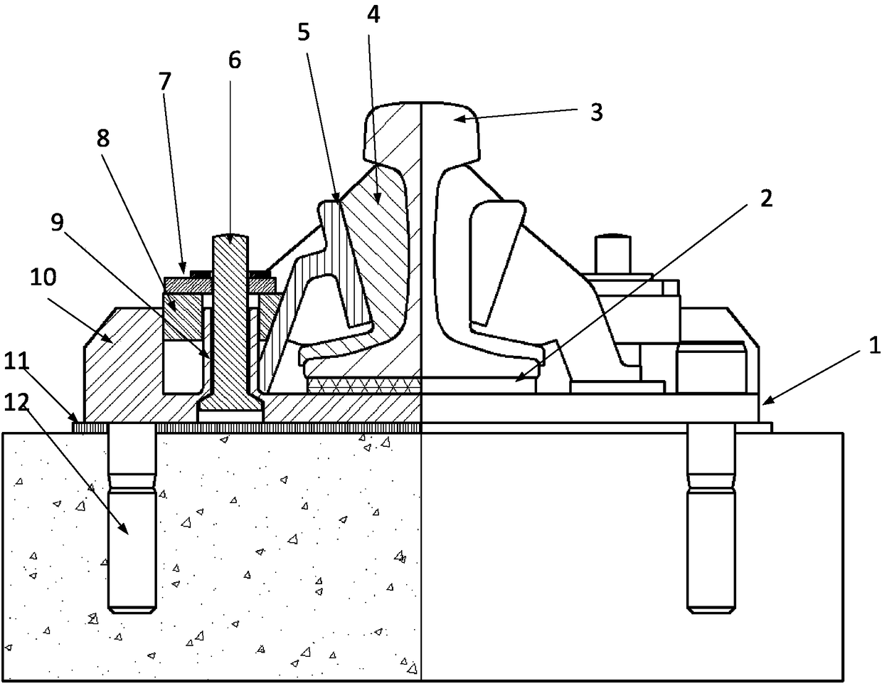
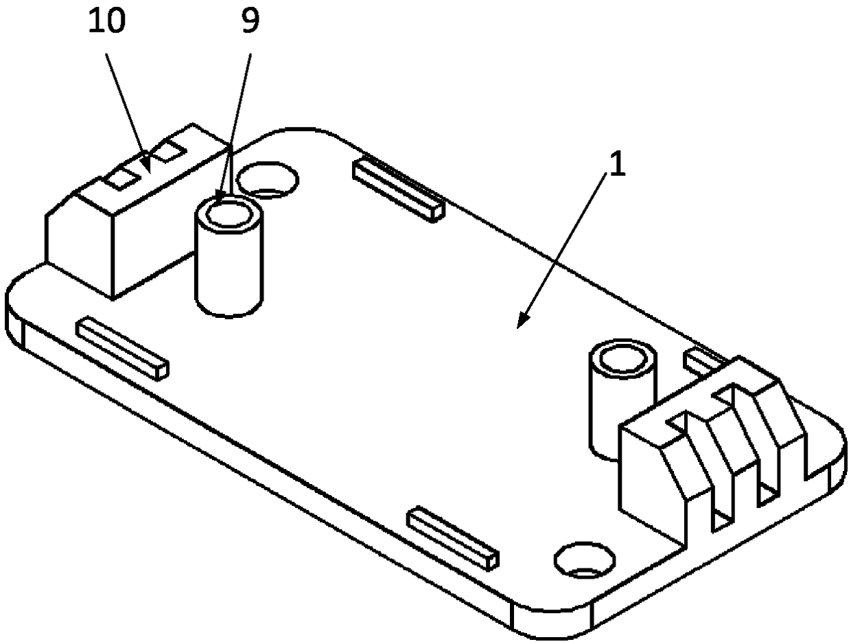
[0060] Such as figure 1 As shown, the first embodiment of the present invention provides a rail vibration damping fastener, which may include a backing plate 1, an elastic body 4, a supporting plate 5, a positioning block 8 and a fastening mechanism; the backing plate 1 is provided with a positioning column 9, The positioning block 8 is provided with a first through hole, and the positioning block 8 is sleeved on the outside of the positioning column 9 through the first through hole; wherein the positioning block 8 can slide along the positioning column 9, that is, the positioning block 8 can be adjusted. Vertical position; the above-mentioned positioning column 9 is preferably arranged vertically on the backing plate 1, that is, the positioning block 8 can move along the positioning column 9 in a vertical direction.

[0061] In this embodiment, the above-mentioned fastening mechanism includes fasteners and a locking cover plate 7. The fasteners are connected to the positioning co...

Embodiment 2

[0080] The second embodiment of the present invention provides a rail vibration damping fastener. The main structure is similar to the first embodiment, and also includes a backing plate, an elastic body, a support plate, a positioning block and a fastening mechanism; for the record of the main structure, please refer to the foregoing The detailed record in the first embodiment; here is to illustrate the difference between the two.

[0081] Such as Picture 9 As shown, in this embodiment, the fasteners are bolts, and the upper part of the positioning column 9 is provided with internal threads; the bolts pass through the locking cover plate and are tightened on the internal threads of the positioning column 9. Wherein, the above-mentioned bolts may be the hexagonal bolts 14 shown in the figure, or bolts of other structural forms.

[0082] In the specific operation, the above-mentioned positioning post 9 can be set as a through hole structure, and the inner surface of the through hol...

Embodiment 3

[0084] The third embodiment of the present invention provides a rail vibration damping fastener. The main structure is similar to the first embodiment, and also includes a backing plate, an elastic body, a support plate, a positioning block and a fastening mechanism; for the record of the main structure, please refer to the foregoing The detailed record in the first embodiment; here is to illustrate the difference between the two.

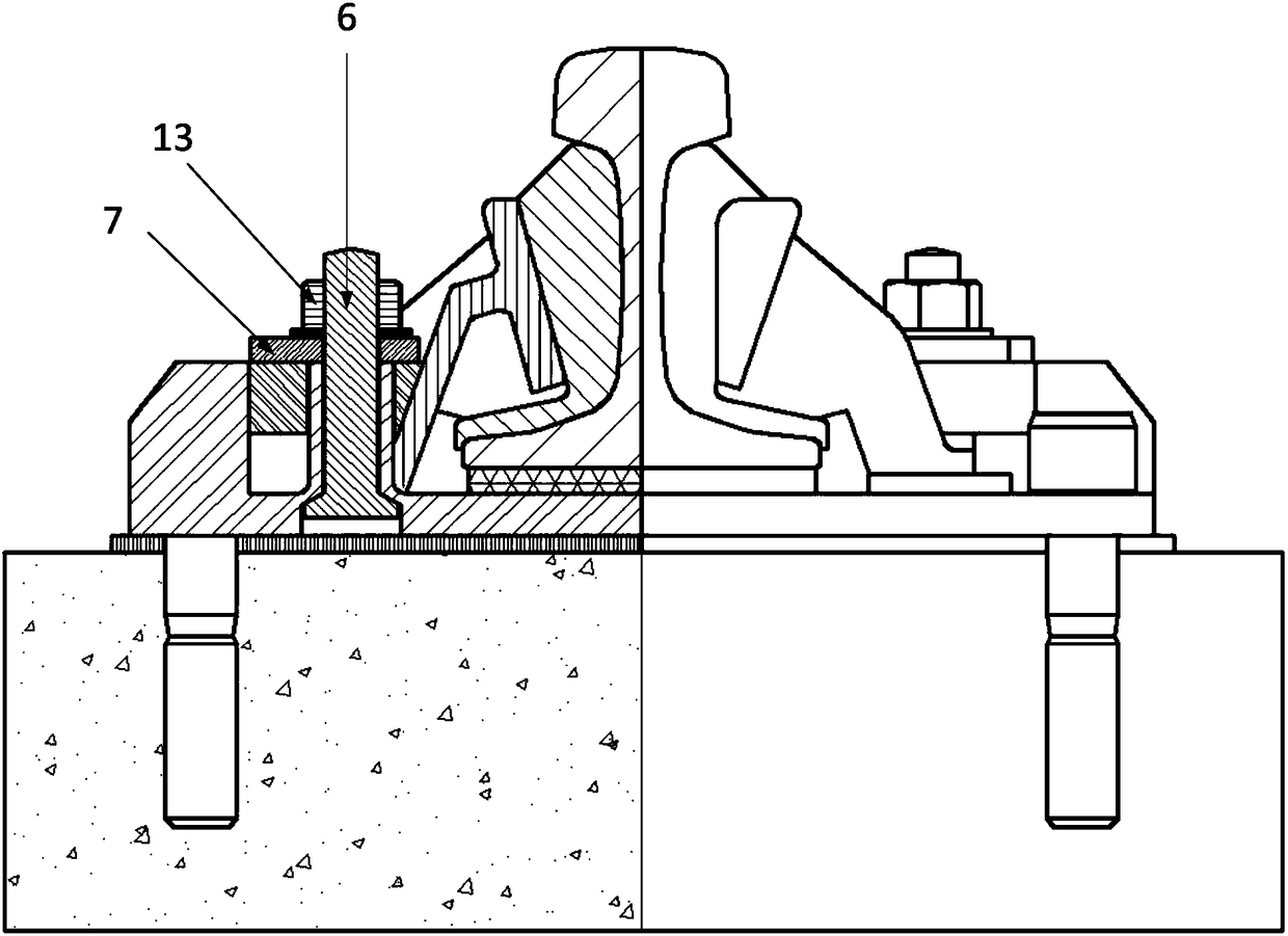
[0085] Such as Picture 10 As shown, in this embodiment, the fastener is a nut 13, and the upper part of the positioning column 9 is provided with an external thread; the nut 13 is screwed on the outer bolt of the positioning column 9, and the lower surface of the nut 13 presses and locks the cover plate. The aforementioned nut 13 can be a common hexagonal nut or a nut of other structural forms.

[0086] In the specific operation, a certain length of external thread can be opened on the upper part of the positioning column 9. After the positioning block...


PUM


Abstract

A rail vibration damping fastener is disclosed in this paper, which comprises a cushion plate, an elastomer, a support plate, a positioning block and a fastening mechanism. The pad plate is provided with a positioning column, the positioning block is provided with a first through hole, and the positioning block is sleeved on the outside of the positioning column through the first through hole. Thefastening mechanism comprises a fastener and a locking cover plate, wherein the fastener is connected with a positioning post, and the fastener presses the positioning block through the locking coverplate; One side of the support plate is connected with the elastomer, the elastomer is fixed at the rail waist of the rail, and the other side of the support plate is abutted on the positioning block; The contact surface between the support plate and the positioning block is an inclined surface, and the top end of the inclined surface is inclined to the side close to the rail; The application canbe applied to the technical field of rail transit, and the application can effectively solve the problems existing in the prior art, and can realize the convenient installation operation of the positioning block, so as to provide the elastomer with sufficient pressing force; Furthermore, the composition of the existing rail vibration damping fastener can be optimized, and the convenient installation and maintenance operation can be realized.

Description

Technical field [0001] This application relates to, but is not limited to, the field of rail transit, especially a rail vibration damping fastener. Background technique [0002] In recent years, with the rapid development of rail transit systems represented by subways and intercity railways, it has effectively alleviated the tension of urban traffic. At the same time, the vibration and noise pollution caused by these transportation methods have also brought people Production and life have brought great troubles. As a connecting part between the rail and the sleeper, rail fasteners not only have the function of fixing the rail, but also their vibration and noise reduction functions have attracted more and more attention. [0003] At present, a series of rail fastener products with vibration and noise reduction functions have been launched on the market. Among many damping fastener products, a damping fastener that clamps and lifts the rail from both sides of the rail has a high da...

Claims


Application Information

Patent Timeline
IPC IPC(8): E01B9/44
CPCE01B9/44E01B2201/04
Inventor 潘涛王勇赵巍
Owner 洛阳科博思新材料科技有限公司
Learn More