
Processing method and non-spherical surface optical element

A processing method and technology of optical components, applied to optical surface grinders, metal processing equipment, manufacturing tools, etc., can solve the problems of time-consuming, expensive, and low polishing removal rate, so as to save process and time, and improve surface accuracy , The effect of high-precision and rapid processing

Inactive Publication Date: 2018-12-11
LASER FUSION RES CENT CHINA ACAD OF ENG PHYSICS
View PDF7 Cites 1 Cited by
  • Summary
  • Abstract
  • Description
  • Claims
  • Application Information

AI Technical Summary

Problems solved by technology

After the aspheric element is ground and shaped, it needs to be polished. In the initial polishing process, it is necessary to improve the surface accuracy of the aspheric optical element from tens of microns to the order of microns while removing subsurface damage. Due to polishing The removal rate is relatively small, correcting the surface shape and removing subsurface damage during the polishing stage is a very time-consuming and unpredictable process, resulting in uncontrollable processing cycle and cost of aspheric optical components
[0005] Although the surface accuracy PV value of aspheric optical elements processed by ultra-high-precision grinding machine tools can reach below 5 μm, ultra-high-precision grinding machine tools are expensive, which greatly increases the cost of high-precision molding of aspheric optical elements

Method used


Image

  • Processing method and non-spherical surface optical element
  • Processing method and non-spherical surface optical element
  • Processing method and non-spherical surface optical element

Examples


Embodiment Construction

[0041] In order to make the purposes, technical solutions and advantages of the embodiments of the present application clearer, the technical solutions in the embodiments of the present application will be clearly and completely described below in conjunction with the drawings in the embodiments of the present application. Obviously, the described embodiments It is a part of the embodiments of this application, but not all of them. The components of the embodiments of the application generally described and illustrated in the figures herein may be arranged and designed in a variety of different configurations.

[0042] Accordingly, the following detailed description of the embodiments of the application provided in the accompanying drawings is not intended to limit the scope of the claimed application, but merely represents selected embodiments of the application. Based on the embodiments in this application, all other embodiments obtained by persons of ordinary skill in the a...


PUM


Abstract

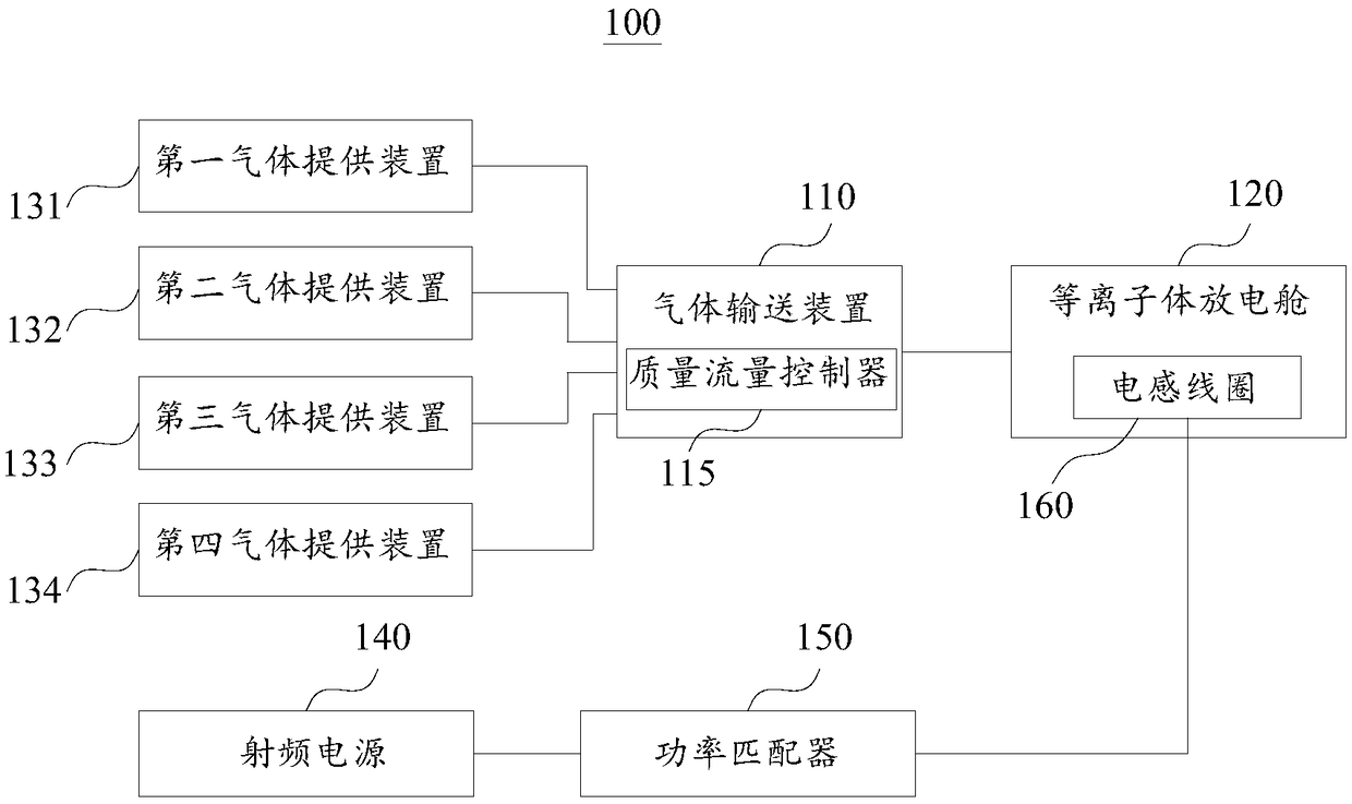
The embodiment of the invention provides a processing method and a non-spherical surface optical element. According to the processing method, the non-spherical surface optical element is processed through plasma jet, wherein the plasma jet is spaced from the non-spherical surface optical element by a predetermined distance. The non-contact jet processing manner can avoid the introduction of subsurface damage during processing and saves the subsequent process and time of removing the subsurface damage.

Description

technical field [0001] The present application relates to the technical field of optical processing, in particular, to a processing method and an aspheric optical element. Background technique [0002] Compared with traditional spherical optical elements, aspheric optical elements have the advantages of improving the relative aperture ratio of the system, expanding the field of view, reducing system composition and weight, eliminating spherical aberration, eliminating coma, and eliminating astigmatism. In addition, it can simplify the optical path It involves improving the optical characteristics and stability of the optical system and reducing the cost of the optical system, so it has a very wide range of applications in the optical field. In related technologies, the processing of aspheric optical elements is realized by milling of grinding wheels. Specifically, a spherical surface closest to the contour of the aspheric surface is first processed on a spherical surface mil...

Claims


Application Information

Patent Timeline
Patent Type & Authority Applications(China)
IPC IPC(8): B24B1/00B24B13/00
CPCB24B1/00B24B13/00
Inventor 金会良许乔李亚国欧阳升王度袁志刚刘志超耿锋王健张清华
Owner LASER FUSION RES CENT CHINA ACAD OF ENG PHYSICS
Learn More