


Quick Research
Generate reliable direction feasibility study reports for your R&D in just a few steps.

Technical Q&A
Discover and master advanced knowledge NOW. Basics, ideas, possibilities, all at once.

Find Solutions
As an expert in R&D theories, this can generate solutions to your technical problems instantly.

Evaluate Feasibility
Analyze your overall solution with one click, know your potential R&D risks in advance.

Monitor Landscape
Get weekly tech updates, stay abreast of the latest tech innovations and key insights.
Rotary locking mechanism for chair
A technology of rotation lock and rotation mechanism, which is applied to vehicle seats, movable seats, chairs with vertically adjustable seats, etc., can solve the problems of inconvenience, friction noise, etc., and achieve the purpose of increasing service life, eliminating wear and tear, improving The effect of user experience
- Summary
- Abstract
- Description
- Claims
- Application Information
AI Technical Summary
Problems solved by technology
Method used
Image

Examples
Embodiment 1
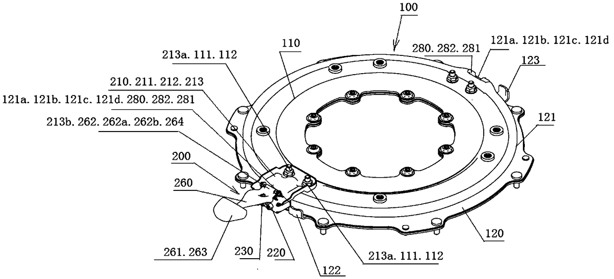
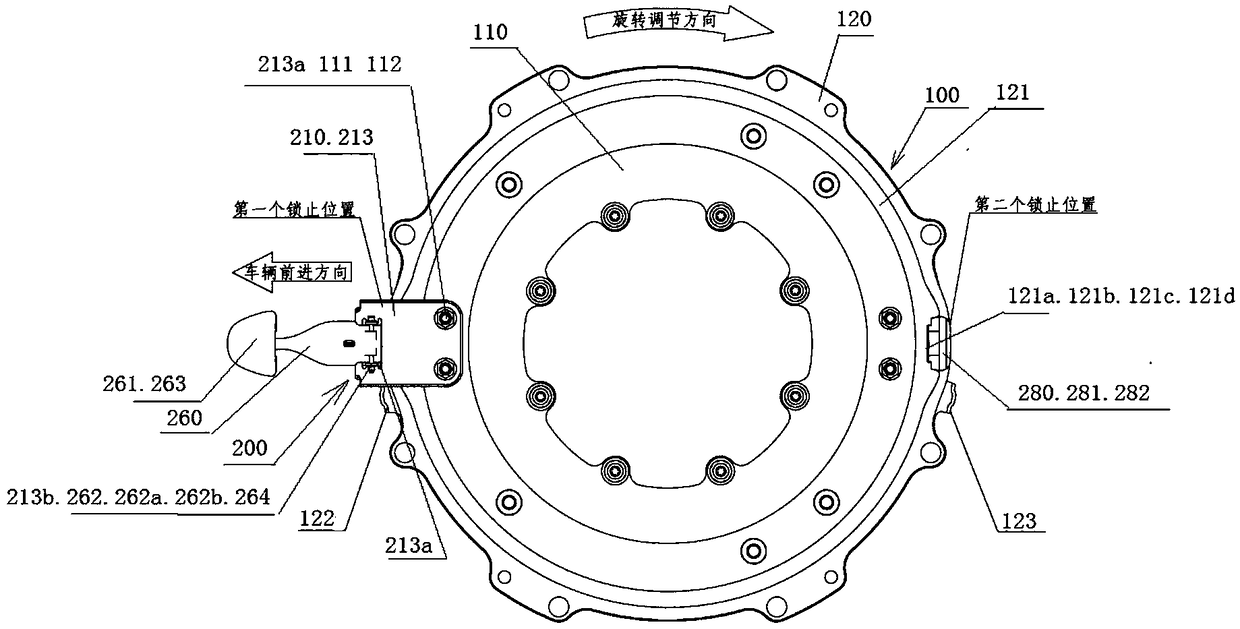
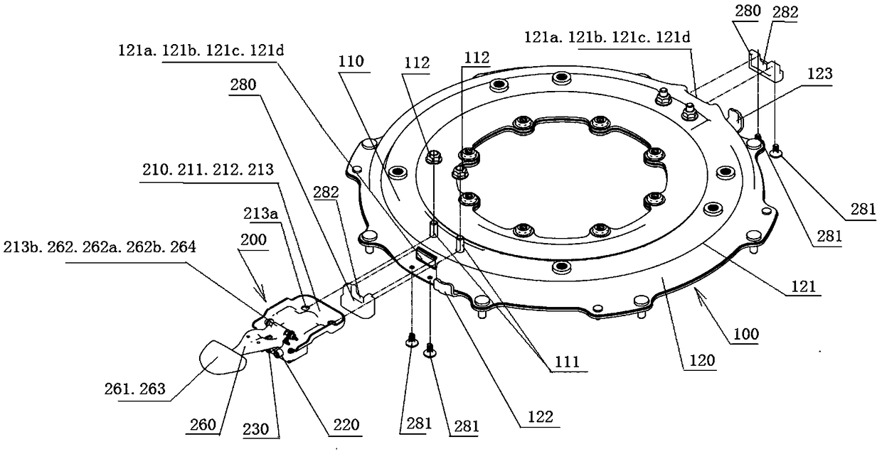
[0056] see Figure 1 to Figure 9 , a seat rotation locking mechanism shown in the figure includes a locking mechanism 200, the locking mechanism 200 is installed on the rotating disk 110 in the seat rotating mechanism 100 so as to follow the rotation of the rotating disk 110. Two lock holes 121a are evenly distributed on the outer circumference 121 of the fixed plate 120 in the seat rotation mechanism 100, and the central angle between the two lock holes 121a is 180°. Each lock hole 121a is a waist-shaped lock hole to accommodate two lock pins at the same time.
[0057] The locking mechanism 200 includes a lock bracket 210 , two lock pins 220 , 230 , two lock pin return springs 240 , 250 , an unlock handle 260 and an unlock handle return spring 270 .
[0058] The lock bracket 210 has a first end surface 211 adjacent to the outer circumference 121 of the fixing plate 120 , a second end surface 212 opposite to the first end surface 211 , and a top surface 213 connecting the fir...
Embodiment 2
[0073] In order to further solve the problem that the ends of the first ends 221, 231 of the two lock pins 220, 230 contact and scratch the outer circumference 121 of the fixed plate 120, this embodiment makes further improvements to Embodiment 1, the improvements are: see Figure 14 In the lock hole 121a, there is a sound-absorbing bush 124. In the locked state, the first ends 221, 231 of the two lock pins 220, 230 are inserted into the sound-absorbing bush 124 under the action of the lock pin return springs 240, 250. The rotary disk 110 is locked.
[0074] see Figure 15 and Figure 16 , set the insertion amount of the first ends 221, 231 of the two lock pins 220, 230 into the silencer bushing 124 to be A2, the outward protrusion 121b on the outer circumference 121 of the fixed disc 120 and the rest of the outer circumference 121 of the fixed disc 120 Part has a surface difference dimension A1, wherein A1 is 2.5-3mm larger than A2, so that in the process of rotation adjust...
PUM
 Abstract
Description
Claims
Application Information
 - R&D Engineer
- R&D Manager
- IP Professional
- Industry Leading Data Capabilities
- Powerful AI technology
- Patent DNA Extraction
Browse by: Latest US Patents, China's latest patents, Technical Efficacy Thesaurus, Application Domain, Technology Topic, Popular Technical Reports.
© 2024 PatSnap. All rights reserved.Legal|Privacy policy|Modern Slavery Act Transparency Statement|Sitemap|About US| Contact US: help@patsnap.com