
Method for detecting motor rotor position and rotation speed based on adaptive sliding mode observer

A technology of self-adaptive sliding mode and motor rotor, which is used in the control of generators, motor generators, and electromechanical transmissions.

Inactive Publication Date: 2018-12-07
UNIV OF SHANGHAI FOR SCI & TECH
View PDF3 Cites 9 Cited by
  • Summary
  • Abstract
  • Description
  • Claims
  • Application Information

AI Technical Summary

Problems solved by technology

With the long-term operation of the motor, affected by many external and internal conditions such as the temperature environment, the motor parameters will undergo various changes under non-ideal conditions, which will gradually cause the accuracy of the estimated results to decrease.

Method used


Image

  • Method for detecting motor rotor position and rotation speed based on adaptive sliding mode observer
  • Method for detecting motor rotor position and rotation speed based on adaptive sliding mode observer
  • Method for detecting motor rotor position and rotation speed based on adaptive sliding mode observer

Examples


Embodiment Construction

[0041] In order to make the technical means, creative features, goals and effects of the present invention easy to understand, the following embodiments will specifically describe a method for detecting the position and speed of the motor rotor based on an adaptive sliding mode observer in the present invention in conjunction with the accompanying drawings.

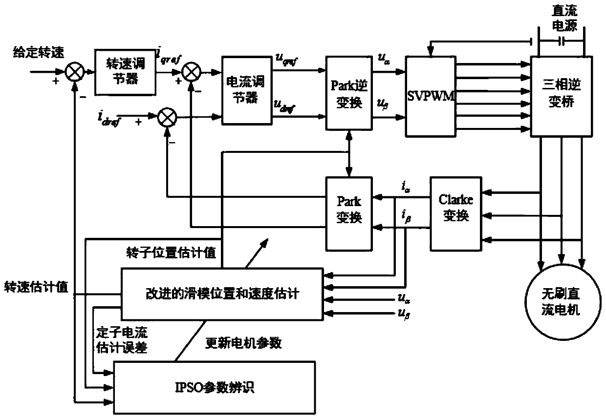
[0042] figure 1 It is a block diagram of a brushless DC motor speed and torque double closed-loop control system.

[0043] Such as figure 1 As shown, the system consists of brushless DC motor, three-phase inverter bridge, space vector pulse width modulation (SVPWM), speed regulator, current regulator, improved sliding mode observer, IPSO parameter identification, field oriented control (FOC) And so on, the field oriented control part includes Park transform, Clark transform, Park inverse transform. Since there is no speed sensor in the system, the stator voltage u in the two-phase static αβ coordinate system is obtained...


PUM


Abstract

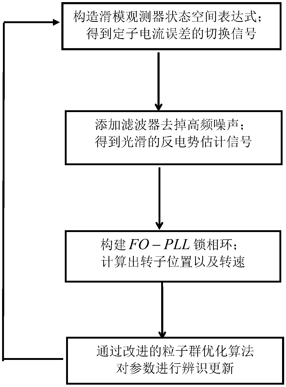
The invention provides a method for detecting the motor rotor position and the rotation speed based on an adaptive sliding mode observer and aims to detect the rotor position and the rotation speed ofa motor. The method comprises steps that S1, a state space expression of the sliding mode observer is constructed to obtain a switching signal of a stator current error; S2, a filter is added to remove the high frequency noise and obtain a smooth back EMF estimation signal; and S3, an FO-PLL phase locked loop is constructed, and the rotor position and the rotation speed are calculated; and S4, stator resistance and stator inductance parameters in the sliding mode observer are identified and updated through the improved particle swarm optimization algorithm. The method is advantaged in that the rotor position and the rotation speed of the brushless DC motor can be detected accurately and instantly.

Description

technical field [0001] The invention specifically relates to a method for detecting the position and rotational speed of a motor rotor based on an adaptive sliding mode observer. Background technique [0002] The motor can be easily controlled by position sensor measurement, but there are problems in volume, cost, casing temperature, detection accuracy, etc. The extensive use of sensors increases the number of electrical connections, which brings certain difficulties to the anti-interference design. Even the most commonly used Hall sensors cannot properly detect when the temperature is too high, which also limits its application range. [0003] It is against the above-mentioned background that the sensorless technology is proposed. Among them, the sliding mode observer can be used to detect the rotor position and speed of the motor. It is based on the idea of ​​sliding mode variable structure. According to the motor model, the error signal in the ordinary control loop is re...

Claims


Application Information

Patent Timeline
IPC IPC(8): H02P21/00H02P21/18H02P6/182
CPCH02P6/182H02P21/0007H02P21/18
Inventor 金爱娟杨晓洁纪晨烨李少龙郑天翔
Owner UNIV OF SHANGHAI FOR SCI & TECH
Learn More