Sharing lock system
A technology of shared lock and electromagnetic lock, which is applied in the field of shared lock system, can solve the problems of easy interception of digital signature instructions, short service life and high cost, and achieve the effect of low cost, long service life and simple structure
- Summary
- Abstract
- Description
- Claims
- Application Information
AI Technical Summary
Problems solved by technology
Method used
Image
Examples
Embodiment 1
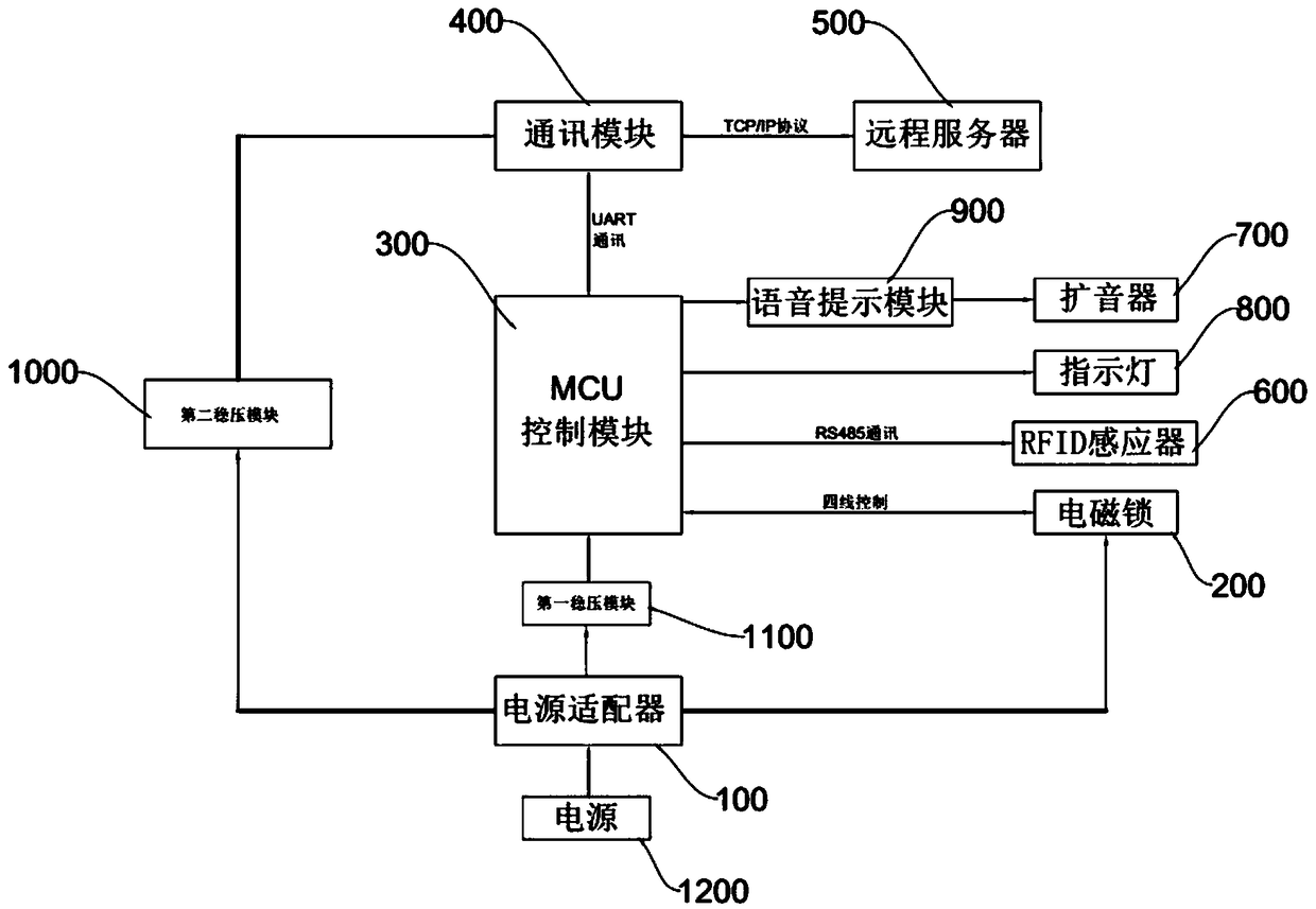
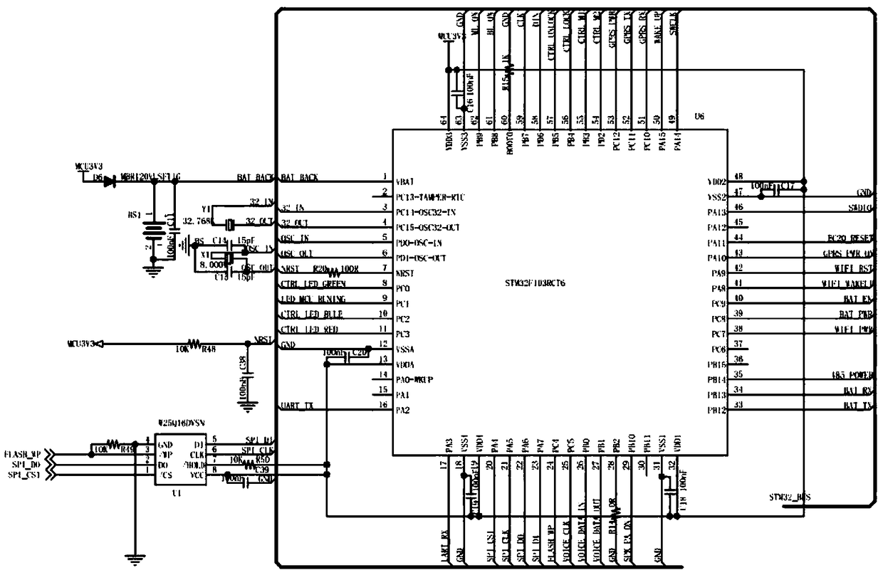
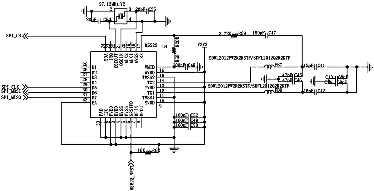
[0029] like figure 1 , figure 2 , image 3 , Figure 4 , Image 6 , Figure 7 , Figure 8 , Figure 9 , Figure 10 and Figure 11 As shown, a shared lock system includes a power supply 1200 and an electromagnetic lock 200, and also includes an MCU control module 300, a communication module 400, a remote server 500, an RFID sensor 600 and a power adapter 100, and the MCU control module 300 is used to control The electromagnetic lock 200 is turned on / off, the MCU control module 300 is connected to the remote server 500 through the communication module 400 for signal transmission, and the MCU control module 300 is connected to the RFID sensor 600 through RS485 communication for related products Induction, the power supply 1200 supplies power to the electromagnetic lock 200 , the MCU control module 300 and the communication module 400 respectively through the power adapter 100 . The communication module 400 breaks away from the traditional wired connection method, and th...
Embodiment 2
[0044] like figure 1 , figure 2 , image 3 , Figure 5 , Image 6 , Figure 7 , Figure 8 , Figure 9 , Figure 10 and Figure 11 As shown, a shared lock system includes a power supply 1200 and an electromagnetic lock 200, and also includes an MCU control module 300, a communication module 400, a remote server 500, an RFID sensor 600 and a power adapter 100, and the MCU control module 300 is used to control The electromagnetic lock 200 is turned on / off, the MCU control module 300 is connected to the remote server 500 through the communication module 400 for signal transmission, and the MCU control module 300 is connected to the RFID sensor 600 through RS485 communication for related products Induction, the power supply 1200 supplies power to the electromagnetic lock 200 , the MCU control module 300 and the communication module 400 respectively through the power adapter 100 . The communication module 400 breaks away from the traditional wired connection method, and th...
PUM
 Abstract
Description
Claims
Application Information
 - Generate Ideas
- Intellectual Property
- Life Sciences
- Materials
- Tech Scout
- Unparalleled Data Quality
- Higher Quality Content
- 60% Fewer Hallucinations
Browse by: Latest US Patents, China's latest patents, Technical Efficacy Thesaurus, Application Domain, Technology Topic, Popular Technical Reports.
© 2025 PatSnap. All rights reserved.Legal|Privacy policy|Modern Slavery Act Transparency Statement|Sitemap|About US| Contact US: help@patsnap.com


