Heterodyne interference optical path structure based on optical fibers and laser vibrometer
A laser vibrometer and heterodyne interference technology, applied in the field of interferometry, can solve the problems of lowering the optical efficiency of the interference system, low system reliability, and difficulty in making the system small, so as to improve the measurement efficiency and enhance the reliability of the interference. The effect of improving performance and accuracy
- Summary
- Abstract
- Description
- Claims
- Application Information
AI Technical Summary
Problems solved by technology
Method used
Image


Examples
Embodiment 1
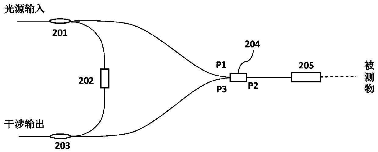
[0063] Such as figure 1 As shown, this embodiment provides a fiber-based heterodyne interference optical path structure, including:
[0064] A first fiber coupler 201, a fiber frequency shifter 202, a second fiber coupler 203, a fiber looper 204, and an optical transceiver 205;
[0065] The first optical fiber coupler 201 is used to divide the received light into two beams and transmit them to the optical fiber frequency shifter 202 and the optical fiber looper 204 respectively;
[0066] The optical fiber frequency shifter 202 receives and modulates the beam transmitted by the first optical fiber coupler 201, shifts the optical frequency of the beam and transmits it to the second optical fiber coupler 203;
[0067] The optical fiber looper 204 includes a first port P1, a second port P2, and a third port P3; the first port P1 receives the light beam transmitted by the first optical fiber coupler 201; the second port P2 is connected to the The optical transceiver 205 is connec...
Embodiment 2
[0076] The difference between this embodiment and Embodiment 1 is that this embodiment supplements the structure of the heterodyne interference circuit in detail, the optical fiber is a polarization-maintaining optical fiber, the first optical fiber coupler 201, the optical fiber frequency shifter 202 , the second fiber coupler 203 and the fiber circulator 204 are polarization maintaining fiber devices, that is, the first fiber coupler 201 and the second fiber coupler 203 are polarization maintaining fiber couplers, fiber frequency shifters 202 is a polarization maintaining optical fiber frequency shifter, and the optical fiber looper 204 is a polarization maintaining optical fiber looper.
[0077] The polarization-maintaining optical fiber and the polarization-maintaining optical fiber and each polarization-maintaining optical fiber device are connected with APC fiber connectors with an angle of 8 degrees; the angle of 8 degrees refers to the inclination angle of the fiber end...
Embodiment 3
[0093] The difference between this embodiment and embodiment 2 is that, as Figure 5 As shown, the optical transceiver 205 in this embodiment includes an optical head and a polarized optical element 2052, the optical head includes a front mirror group 2053 and a rear mirror group 2054, and the light beam transmitted by the second port P2 passes through the rear mirror group The lens group 2054 is focused to the first focal point and projected to the polarizing optical element 2052 through the front lens group 2053 . Specifically, the rear mirror group 2054 and the front mirror group 2053 are coaxially placed successively at the front end of the light end face, the Gaussian beam output by the optical fiber is focused to the first focal point through the rear mirror group 2054, and the front mirror group 2053 images the focused spot of the first focal point to The surface of the object to be measured. There is an object-image conjugate relationship between the measured point an...
PUM
| Property | Measurement | Unit |
|---|---|---|
| Insertion loss | aaaaa | aaaaa |
Abstract
Description
Claims
Application Information
 - R&D
- Intellectual Property
- Life Sciences
- Materials
- Tech Scout
- Unparalleled Data Quality
- Higher Quality Content
- 60% Fewer Hallucinations
Browse by: Latest US Patents, China's latest patents, Technical Efficacy Thesaurus, Application Domain, Technology Topic, Popular Technical Reports.
© 2025 PatSnap. All rights reserved.Legal|Privacy policy|Modern Slavery Act Transparency Statement|Sitemap|About US| Contact US: help@patsnap.com