
Deep-fuze-hole-provided thin-wall shell warhead composite powder charging method

A thin-walled shell and warhead technology, which is applied to ammunition, weapon accessories, offensive equipment, etc., can solve the problems of uneven distribution of pressure charge density in the mouth fuze chamber, low charge density at the mouth, and low production efficiency. To achieve the effect of less charging defects, good charging quality and high production efficiency

Active Publication Date: 2018-12-07
HENAN NORTHERN HONGYANG ELECTROMECHANICAL CO LTD
View PDF2 Cites 1 Cited by
  • Summary
  • Abstract
  • Description
  • Claims
  • Application Information

AI Technical Summary

Problems solved by technology

However, especially the shell wall thickness of the warhead of a large-caliber guided projectile is usually relatively thin. If the ordinary direct pressure charging method is adopted and the charge mold is used to charge the charge, due to the high pressure of the charge (when the shell is filled with explosives, Explosive compression molding pressure is as high as 2MPa~2.5MPa), which will cause deformation of the shell, resulting in unqualified products, and requires multiple mold changes for staged pressing, resulting in low production efficiency
Since the mouth of the shell of the warhead of the guided projectile is small, the diameter of the inner cavity is large, and there is a deep fuze hole under the powder surface of the mouth, if the fuze chamber is pressed and formed by an ordinary direct pressure mold, it will be difficult to eject the mold. Moreover, the distribution of the pressure charge density in the mouth fuze chamber is uneven, resulting in low charge density in the mouth

Method used


Image

  • Deep-fuze-hole-provided thin-wall shell warhead composite powder charging method
  • Deep-fuze-hole-provided thin-wall shell warhead composite powder charging method
  • Deep-fuze-hole-provided thin-wall shell warhead composite powder charging method

Examples


Embodiment Construction

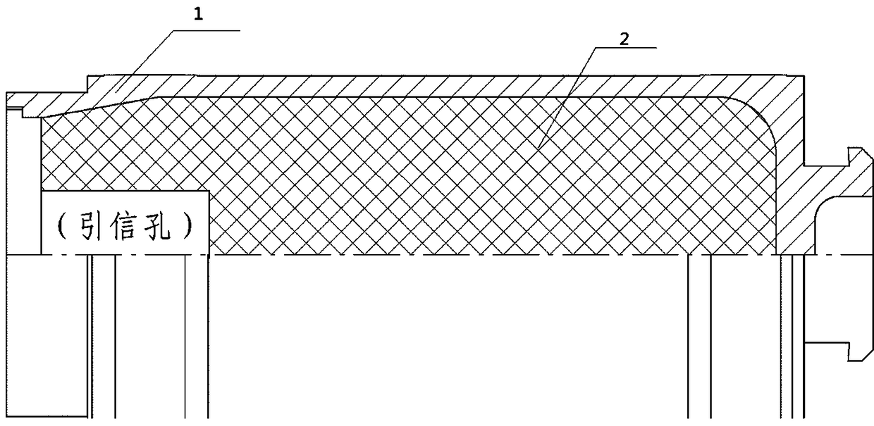
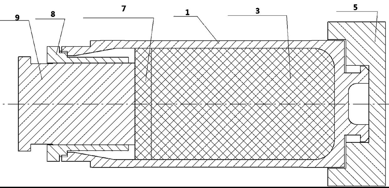
[0027]The following will be described in detail in conjunction with the technical solutions in the embodiments of the present invention: the present invention proposes a method for composite charging of thin-walled shell warheads with deep fuze holes. The composite charging method of combining charges is used to charge the warhead shell with deep fuze hole and thin-walled shell with explosives, see Figure 1 to Figure 6 As shown, the specific implementation steps are as follows:

[0028] Step (1) Shell 1 feeding: transport the packing box containing the warhead shell 1 into the workshop, take out the shell 1 from the box and place it on the workbench;

[0029] Step (2) Weighing the shell 1: first number each shell 1, then use an electronic scale to weigh the mass m1 (g) of each warhead shell 1 and make a record;

[0030] Step (3) Measure the volume of the shell 1: inject clean tap water into the warhead shell 1 with a water pipe, and stir continuously with a wooden stick to r...


PUM

PropertyMeasurementUnit
diameteraaaaaaaaaa
densityaaaaaaaaaa
depthaaaaaaaaaa

Abstract

The invention discloses a deep-fuze-hole-provided thin-wall shell warhead composite powder charging method. According to the technical scheme, a step-by-step powder press charging technological manneris adopted for shell powder charging (a screw rod with the outer diameter being 60 mm is used), then a direct powder press charging method is used at an opening part for three times of powder chargesupplementing (a specially-designed powder pressing die is used), and fuze hole bottom powder face molding (one time of powder pressing molding is carried out) and fuze hole molding (two times of power pressing molding are carried out) are sequentially carried out. According to the powder charging method, the problem that a thin-wall shell is prone to deformation in the powder pressing charging process in the powder charging process is solved, the powder charging density of a large-size inner cavity shell is guaranteed, the powder charging quality is improved, the technological safety and theemission safety of the powder charging process are improved, meanwhile, the production efficiency is improved, the production cost is reduced, the technical problem about how to press and mold a deepfuze hole and the like is solved, and the method has the reference and popularization effects on various deep-fuze-hole-provided thin-wall shell warhead composite powder charging.

Description

technical field [0001] The invention belongs to the technical field of filling high-energy explosives into the casing of a warhead of a weapon and ammunition, and in particular relates to a compound charging method for a warhead of a thin-walled casing with deep fuze holes. Background technique [0002] In order to comply with the trend of new military reforms, countries all over the world are actively exploring ways to improve and improve the function of artillery. How to improve the strike accuracy of existing artillery and minimize ammunition consumption has become a new topic for the development of new artillery systems. However, conventional The hit error of artillery shells will inevitably increase with the increase of range. In order to improve the accuracy of artillery long-distance suppression, the development of long-range guided artillery shells has become an inevitable trend. The development of high-tech, especially microelectronics technology, optoelectronics te...

Claims


Application Information

Patent Timeline
Patent Type & Authority Applications(China)
IPC IPC(8): F42B33/02
CPCF42B33/025
Inventor 佘新继张保良蒋俊涛段召明甘桃元陈砚李哲胡志婉
Owner HENAN NORTHERN HONGYANG ELECTROMECHANICAL CO LTD
Learn More