A hydraulic blasting method for an angle steel structure transmission tower located in a mountainous area

A technology of hydraulic blasting and power transmission tower, which is applied in the field of blasting, which can solve the problems of poor blasting effect, high risk, and inability to weld, etc., and achieve the effects of improving blasting damage, ensuring blasting effect, and shortening blasting cycle

Active Publication Date: 2020-03-10
ARMY ENG UNIV OF PLA +1
View PDF4 Cites 0 Cited by
  • Summary
  • Abstract
  • Description
  • Claims
  • Application Information

AI Technical Summary

Problems solved by technology

[0003] However, when constructing UHV transmission towers, most of the old iron towers are on the same path as the newly built new iron towers, and the original line ground wires and iron towers must be removed before construction can begin.
The dismantling of angle steel laps in our country is still in its infancy and needs to be dismantled by workers, which is labor-intensive, low-efficiency, and highly dangerous.
In the angle steel truss, it is impossible to blast through the hole, only exposed blasting, a large part of the energy is dissipated into the air, and the blasting effect is poor
Since the transmission tower is located in a mountainous area, there is not enough electricity, and welding cannot be carried out on site. Moreover, the transportation in the mountainous area is inconvenient, and it is impossible to transport materials in large quantities.

Method used


Image

  • A hydraulic blasting method for an angle steel structure transmission tower located in a mountainous area
  • A hydraulic blasting method for an angle steel structure transmission tower located in a mountainous area

Examples


Embodiment Construction

[0017] The present invention will be further described below in conjunction with the accompanying drawings.

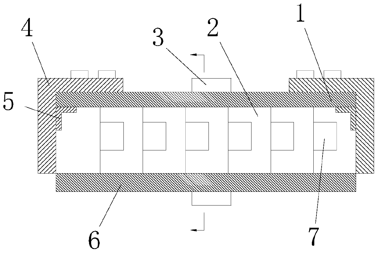
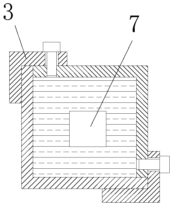
[0018] Such as figure 1 and figure 2 As shown, the hydraulic blasting method of the angle steel structure transmission tower located in the mountainous area of ​​the present invention comprises the following steps:

[0019] (1) According to the structure of the transmission tower, process the first angle steel 1, the second angle steel 3, the third angle steel 4 and the fourth angle steel 5 of suitable size, and weld the fourth angle steel 5 to the two ends inside the first angle steel 1;

[0020] (2) punch holes at the first angle steel 1, the second angle steel 3, the third angle steel 4 and the fourth angle steel 5 at suitable positions, prepare water bag 2, charge bag 7, nonel detonator;

[0021] (3) The blasting device is transported to the transmission tower, the first angle steel 1 is connected with the angle steel 6 to be blasted through the second angle ste...


PUM


Abstract

The invention discloses a hydraulic blasting method for an angle steel structure power transmission tower in a mountainous area. The hydraulic blasting method comprises the following steps that (1) pieces of angle steel with the suitable size are machined according to the structure of the power transmission tower; (2) the suitable positions of the pieces of angle steel are punched, and water bags,cartridge bags and detonating pipe detonators are prepared; (3) a blasting device is transported to the power transmission tower, the first angle steel is connected with the to-be-blasted angle steelto form a cylindrical structure, and the pieces of third angle steel are mounted at the bottom of the cylindrical structure; (4) the water bags and the cartridge bags are alternately placed into thecylindrical structure, and the cartridge bags are guided out of the cylindrical structure through the detonating pipe detonators; (5) the cylindrical structure is sealed at the top through the piecesof third angle steel; and (6) protection, evacuation and vigilance are conducted, and blasting can be conducted after preparing work before blasting is completed. According to the hydraulic blasting method, only the pieces of angle steel and bolts need to be fixed into the cylindrical structure, the water bags and the cartridge bags are placed in the closed space, through incompressibility of liquid water, the blasting damage degree is increased greatly, and the blasting effect can be ensured.

Description

technical field [0001] The invention relates to a hydraulic blasting method for an angle steel structure transmission tower located in a mountainous area, belonging to the field of blasting. Background technique [0002] According to the plan, my country will build dozens of UHV DC projects in the next 10-20 years, and gradually form a UHV AC-DC hybrid power grid, which will supply power to the central and eastern load centers through UHV DC and AC systems. In order to alleviate the problems faced by the multi-infeed DC system, such as insufficient reactive power support capacity of the receiving end grid, and the dense sending system causing the short-circuit current to cross the line, UHV layered DC has become a new DC access mode. Compared with conventional UHV DC, the main difference is that the high-end converter transformer and low-end converter transformer on the inverter side are respectively connected to 500kV and 1000kV power grids, and the AC filter and reactive p...

Claims


Application Information

Patent Timeline
Patent Type & Authority Patents(China)
IPC IPC(8): F42D3/00
CPCE04H12/348
Inventor 龙源钟明寿程良玉高福银殷勤赵长啸陈德志李本伟马华源
Owner ARMY ENG UNIV OF PLA
Why Eureka
Try Eureka