Cantilever end control device and control method for towing construction of curved light I-beam bridge

A control device and I-beam technology, which is applied in bridges, bridge construction, erection/assembly of bridges, etc., can solve the problem of large deflection at the cantilever end of the main girder, which is difficult to reduce the negative bending moment of the fulcrum of the beam body, and the deformation of the inner and outer ends of the beam end Inconsistency, inability to be at the same elevation, etc., to achieve the effect of less difficulty in connection, light weight, and simple structure

Pending Publication Date: 2018-12-07
HEBEI UNIV OF TECH
View PDF0 Cites 2 Cited by
  • Summary
  • Abstract
  • Description
  • Claims
  • Application Information

AI Technical Summary

Problems solved by technology

However, if the beam body is a light curved I-beam, the self-weight of the conventional steel guide beam is almost the same as that of the beam body. At this time, the advantage of light weight and high strength of the steel guide beam compared with the concrete beam, steel box girder and other heavy beams is no longer Existence, the large deflection of the cantilever end of the main beam and the difficulty of reducing the negative bending moment of the fulcrum of the beam body lead to the problems of large internal force in the section of the beam body and difficulty in passing the pier during the construction process
Especially for curved light-weight I-beam bridges, due to the inherent bending-torsion coupling effect of the curved beam structure itself during the dragging process, the deformation of the inner and outer ends of the beam end is inconsistent and cannot be at the same elevation, which is difficult to solve by the conventional beam guide method

Method used


Image

  • Cantilever end control device and control method for towing construction of curved light I-beam bridge
  • Cantilever end control device and control method for towing construction of curved light I-beam bridge
  • Cantilever end control device and control method for towing construction of curved light I-beam bridge

Examples


Embodiment Construction

[0020] Specific examples of the present invention are given below. The specific embodiments are only used to further describe the present invention in detail, and do not limit the protection scope of the claims of the present application.

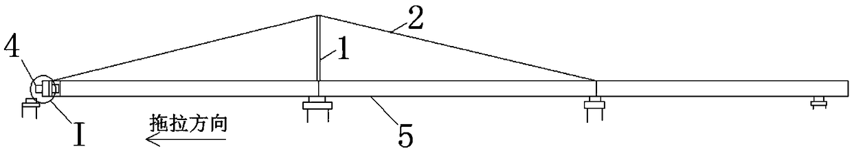
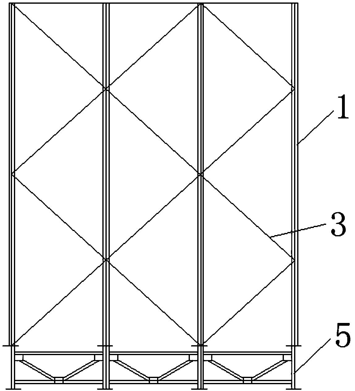
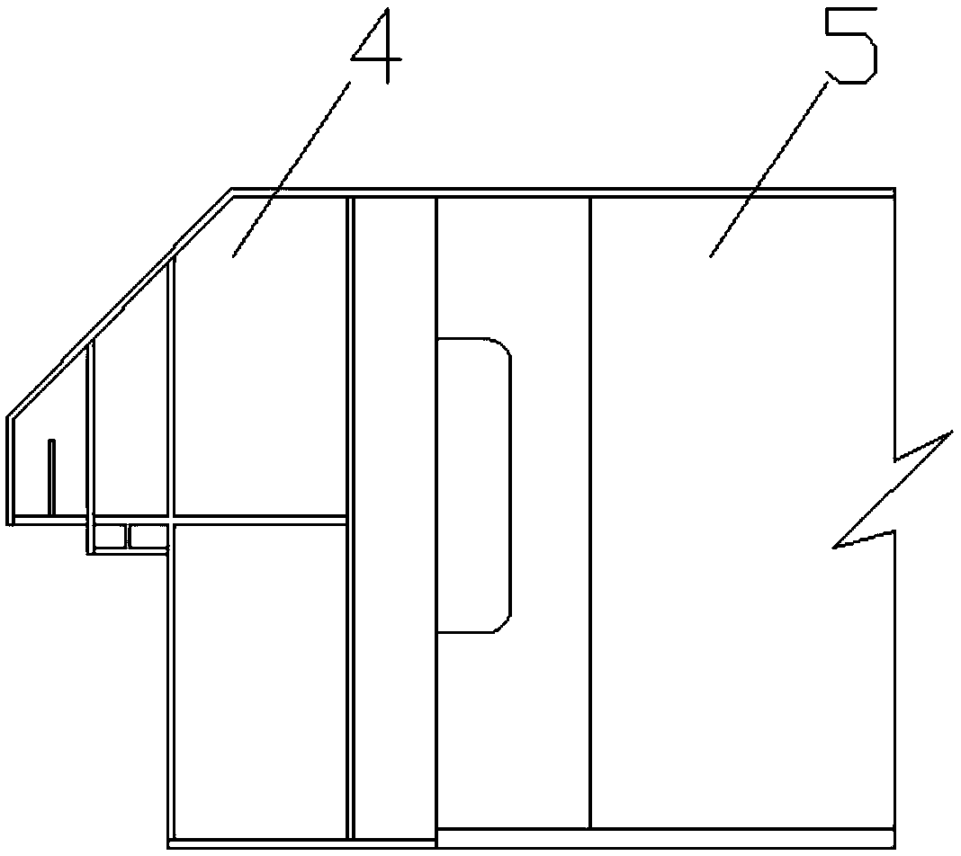
[0021] The invention provides a cantilever end control device for the dragging construction of a curved light-duty I-shaped steel girder bridge (referred to as the device, see Figure 1-3 ), it is characterized in that the device includes a tower 1, a drag cable 2 and a short nose bridge 4; a tower 1 is installed on each longitudinal I-beam of the I-beam 5, and the tower 1 is located at the front two spans of the I-beam 5 in the pulling direction At the middle beam, several towers 1 are evenly arranged along the direction of the bridge; the towers 1 are connected by tower connectors 3 to form a tower frame; one end of the cable 2 is connected to the short nose bridge 4 by a connector, and the middle part is erected on the tower 1. The top ...


PUM


Abstract

The invention discloses a cantilever end control device and a control method for towing construction of a curved light-weight I-beam bridge. The device comprises a tower, a cable and a short nose bridge; A tower is installed on each longitudinal I-beam of the I-beam, and the tower is located at the middle beam two spans in front of the I-beam pulling direction; one end of the stay cable is connected with a short nose beam through a connector, the middle part is erected on the top end of the tower, and the other end is connected with a cross beam of an adjacent span of the connected tower through a connector; the short nose beam is arranged at the front cantilever end in the pulling direction of the i-beam. The combined method of short nose beam and cable can fully adapt to the characteristics of light dead weight and curved alignment of I-beam bridge, and solve the problems that the conventional long guide beam cannot meet the requirements of the downward deflection of the cantilever end and the inherent torsional deformation of the curved beam end in the whole dragging process.

Description

technical field [0001] The invention relates to the technical field of bridge engineering, in particular to a cantilever end control device and a control method for drag construction of a curved light-duty I-shaped steel girder bridge. Background technique [0002] The guide girders used in the dragging construction of existing girder bridges are mostly longer steel guide girders, with a length of about 0.7 times the single-span span, which has a good effect on improving the mechanical properties of the bridge dragging process and lifting the front fulcrum. However, if the beam body is a light curved I-beam, the self-weight of the conventional steel guide beam is almost the same as that of the beam body. At this time, the advantage of light weight and high strength of the steel guide beam compared with the concrete beam, steel box girder and other heavy beams is no longer Existence, the large deflection of the cantilever end of the main beam and the difficulty of reducing th...

Claims


Application Information

Patent Timeline
Patent Type & Authority Applications(China)
IPC IPC(8): E01D21/00
CPCE01D21/00
Inventor 黄海新何金玮申浩伟
Owner HEBEI UNIV OF TECH
Why Eureka
Try Eureka