Dry vertical grading impeller

A classification impeller, vertical technology, applied in solid separation, chemical instruments and methods, separation of solids from solids by air flow, etc. Achieve the effect of improving classification accuracy, reducing classification particle size and improving classification efficiency

Pending Publication Date: 2018-12-07
SHANDONG DALIER HEAVY IND CO LTD
View PDF7 Cites 0 Cited by
  • Summary
  • Abstract
  • Description
  • Claims
  • Application Information

AI Technical Summary

Problems solved by technology

[0004] The existing dry-type vertical classifying impeller has the following problems in the classifying process: First, when the airflow carries the powder into the classifying area from the air inlet at the lower part of the impeller, it will have a large impact on the lower part of the classifying field, and the classifying The stability of the field is destroyed, and the powder flows turbulently in the grading field around the bottom of the impeller, which leads to unqualified powder entering the interior of the impeller
The second is that the grading impeller is installed on the top of the pulverizer. Since the gas-solid mixed powder is supplied from the bottom up, that is, from the bottom of the impeller upward, this feeding state cannot make the state of the grading field at the top of the impeller consistent with other parts. , the specific state phenomenon is: during the upward movement of the gas-solid mixed powder, since the fine powder in the gas-solid mixed powder continuously enters the grading impeller, the coarse particles in the gas-solid mixed powder in the top grading field are relatively More, coarse particles are easy to enter from the top of the grading impeller, then there will be more large particles mixed in the product, it is difficult to achieve ultra-fine grading of the powder, reducing the grading accuracy, and the grading efficiency is not high

Method used


Image

  • Dry vertical grading impeller
  • Dry vertical grading impeller

Examples


Embodiment Construction

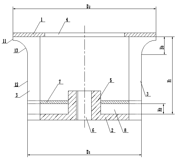
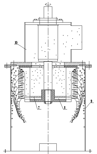
[0015] like figure 1 As shown, the dry vertical grading impeller includes a top plate 1, a chassis 2, and a plurality of blades 3 connected to the top plate 1 and the bottom plate 2 and evenly distributed around the ring. The center of the top plate 1 is provided with an impeller shaft penetration hole 4, The central portion of the top surface of the chassis 2 protrudes upwards to form a boss 5, and the boss 5 is provided with an impeller shaft mounting hole 6. The boss 5 is fixedly connected with a spacer 7 spaced apart from the chassis 2, the edge of the spacer 7 is fixedly connected with the blade 3, and the spacer 7 is arranged in parallel with the chassis 2, so that there is a gap between the chassis and the spacer. A buffer space 8 that communicates with the outside of the impeller and does not communicate with the inside of the impeller through the gap between adjacent blades is formed between them. The outer side of described blade 3 is made of the short straight sect...


PUM


Abstract

The invention discloses a dry vertical grading impeller. The dry vertical grading impeller comprises a top disc, a bottom disc and multiple blades connected to the top disc and the bottom disc and evenly and annularly distributed. An impeller shaft penetrating hole is formed in the center portion of the top disc. The center portion of the top face of the bottom disc protrudes and extends upwards to form a boss. An impeller shaft mounting hole is formed in the boss. A spacer disc is fixedly connected to the boss, wherein the spacer disc and the bottom disc are spaced. The edge of the spacer disc and the blades are fixedly connected together. The outer side of each blade is composed of a short straight side segment at the top, a long straight side segment on the lower portion and an arc sidesegment in smooth connection with the short straight side segment and the long straight side segment. The long straight side segments of the blades are closer to the axis of the grading impeller thanthe short straight side segments, and therefore the grading impeller becomes an unequal-diameter impeller composed of a thin and long segment small in diameter, a gradual thick segment with the diameter gradually increased from bottom to top and a short and thick segment large in diameter. The impeller of the structure is simple in structure and has the advantages of being high in grading precision and grading efficiency, and ultrafine grading can be achieved.

Description

technical field [0001] The invention relates to a dry vertical classification impeller. Background technique [0002] In the application of powder materials, the dry vertical airflow classifier is widely used because of its simple structure. During the grading process, the main technical indicators are the corresponding grading granularity concentration and grading efficiency. [0003] During the airflow classification process, the gas-solid mixed powder continuously rushes to the impeller at a certain speed, and the fine-grained powder passes through the impeller, while the coarse-grained powder is thrown out due to the large centrifugal force, thus achieving the classification. Purpose. This process is actually a process in which the mixed powder continuously rushes to the impeller and the coarser particles are continuously thrown out, and it is also a process in which the coarse and fine particles collide in reverse; due to the effect of the collision, the coarse and fi...

Claims


Application Information

Patent Timeline
Patent Type & Authority Applications(China)
IPC IPC(8): B07B7/083B07B11/00
CPCB07B7/083B07B11/00
Inventor 吕勇李文泉刘恒明
Owner SHANDONG DALIER HEAVY IND CO LTD
Why Eureka
Try Eureka