
A kind of photolysis oxidative fission VOC treatment device

A treatment device and photolysis technology, applied in gas treatment, chemical instruments and methods, separation methods, etc., can solve the problems of low removal efficiency, complex structure of the device, high maintenance cost, etc., and achieve improved treatment effect, sufficient light receiving, and maintenance low cost effect

Active Publication Date: 2020-09-18
褚福友 +1
View PDF10 Cites 0 Cited by
  • Summary
  • Abstract
  • Description
  • Claims
  • Application Information

AI Technical Summary

Problems solved by technology

[0004] At present, it mainly focuses on the combined use of various purification technologies, such as the application number CN200810060790.7, the name of the invention is: a long-term purification device for indoor air compound pollution, mainly using electrostatic dust removal, ultraviolet sterilization, TiO 2 A combined process for photocatalytic removal of chemical pollutants and some microorganisms, but the device is complex and the removal efficiency is not high
Application number CN201510466896.7, the name of the invention is: a waste gas treatment device and a waste gas treatment method, mainly including an absorption tower, a gas-liquid mixing device and a delivery device, an ultraviolet oxidation device and a release device connected to the ultraviolet oxidation device, which integrates the adsorption , catalytic oxidation and spray absorption in one, but the structure of the device is complicated and the maintenance cost is high

Method used


Image

  • A kind of photolysis oxidative fission VOC treatment device
  • A kind of photolysis oxidative fission VOC treatment device
  • A kind of photolysis oxidative fission VOC treatment device

Examples


Embodiment 1

[0033] like figure 1 As shown, the VOC waste gas treatment device includes a reaction box 1, an air inlet 2, a catalyst layer 3, an ultraviolet lamp 4, a VOC content detector 5, an air outlet 6, and the air inlet 2 is arranged on the lower left of the reaction box 1 side, the catalyst layer 3 is arranged above the air inlet 2, each ultraviolet lamp 4 is arranged above the corresponding catalyst layer 3, and the gas outlet 6 is arranged on the upper right of the reaction box 1, which is higher than the catalyst layer 3, and the gas outlet Set VOC content detector 5. In the experiment, 563mg / m of VOC gas was introduced 3 and heavy metal industrial waste gas, turn on the ultraviolet lamp 4 to irradiate for 10 minutes, after the treatment is completed, measure the remaining VOC content through the VOC content detector at the gas outlet 6, and the actual treatment air volume is 3700M 3 / H, dwell time 3 seconds.

[0034] Preparation of catalyst layer:

[0035] 1) TiO 2 Preparat...

Embodiment 2-10

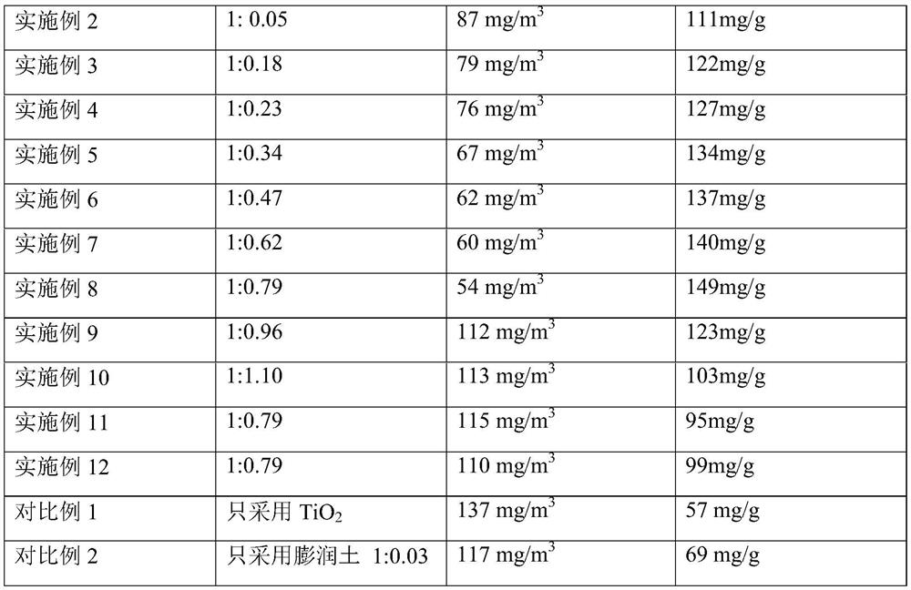
[0040] Adsorption substrate / TiO according to Table 1 2 The loading of catalyst is carried out, and treatment method and treatment air volume are all identical with embodiment 1, and the VOC remaining amount that obtains finally is as shown in table 1 below.

Embodiment 11

[0042] Other conditions are the same as in Example 8, except that the preparation of the adsorption substrate does not use temperature programming, but directly heats the mixture of bentonite and chitosan to 450 ° C for 2 hours to prepare a carbon / bentonite composite material as an adsorption base.


PUM


Abstract

The invention relates to the technical field of waste-gas treatment and particularly relates to a device for photolytic oxidation treatment of VOC (Volatile Organic Compound) pollutants. The device comprises a reaction box body 1, a gas inlet 2, a catalyst layer 3, a catalytic light source 4 and a gas outlet 6, wherein the gas inlet 2 is positioned at the left and lower part of the reaction box body 1; the gas outlet 6 is arranged at the right and upper part of the reaction box body 1 and is higher than the catalytic layer 3; one or more catalyst layers 3 parallel to the bottom surface of thereaction box body 1 is / are arranged above the gas inlet 2; each catalyst layer 3 corresponds to a group of catalytic light sources 4 which are arranged above the corresponding catalyst layer 3. The device has the beneficial effects that by adoption of the photocatalyst prepared by a specific preparation method, a higher VOC treatment effect can be realized only by a simple device, and simultaneously certain treatment capability for heavy metal ions is achieved and the maintenance cost is low.

Description

technical field [0001] The invention relates to the technical field of waste gas treatment, in particular to a device for photolytic oxidation treatment of VOC pollutants. Background technique: [0002] In recent years, with the rapid development of my country's industry, while promoting economic development, it also produces a large amount of VOC (volatile organic compound) waste gas, which not only pollutes the environment, but also seriously affects human health. At present, the treatment of VOC waste gas mainly adopts activated carbon method, spray absorption method, photolysis method and so on. Among them, the photodecomposition method can be divided into two forms: one is direct ultraviolet light to decompose VOCs; the other is photocatalytic oxidation. [0003] Among them, photocatalytic oxidation reaction conditions are mild, the reaction device is simple, and the treatment effect is good, so it has been widely used. [0004] At present, it mainly focuses on the co...

Claims


Application Information

Patent Timeline
Patent Type & Authority Patents(China)
IPC IPC(8): B01D53/86B01D53/64B01D53/44
CPCB01D53/8665B01D53/8687B01D2253/102B01D2253/11B01D2255/20707B01D2255/802B01D2257/708B01D2259/804
Inventor 褚福友于静
Owner 褚福友
Learn More