
Humidifier and split air conditioner

A humidifier and cavity technology, applied in the field of air humidification devices, can solve the problems of high requirements for placement, deposition of dirt in the humidifier, growth of harmful microorganisms, etc., and achieve the effect of avoiding deposition of dirt

Active Publication Date: 2018-11-30
AUX AIR CONDITIONING LTD BY SHARE LTD
View PDF7 Cites 1 Cited by
  • Summary
  • Abstract
  • Description
  • Claims
  • Application Information

AI Technical Summary

Problems solved by technology

At present, most of the humidifiers on the market have their mist outlets located above the humidifier, and in order to achieve humidification in all directions of the room, a circumferential mist outlet structure has been adopted, which has the following problems: 1. The top of the humidifier is easy to accumulate Water will cause the growth of harmful microorganisms, which is not conducive to the sanitation of the humidifier; 2. The mist outlet hole is easy to enter the dust, resulting in the deposition of dirt inside the humidifier, which is not conducive to the sanitation of the humidifier; 3. The humidifier has high requirements for placement. It usually needs to be placed in the middle area of ​​the room away from the wall to prevent the mist from being sprayed on the wall and cause the wall to be damp and moldy, so the applicability is poor

Method used


Image

  • Humidifier and split air conditioner
  • Humidifier and split air conditioner
  • Humidifier and split air conditioner

Examples


Embodiment 1

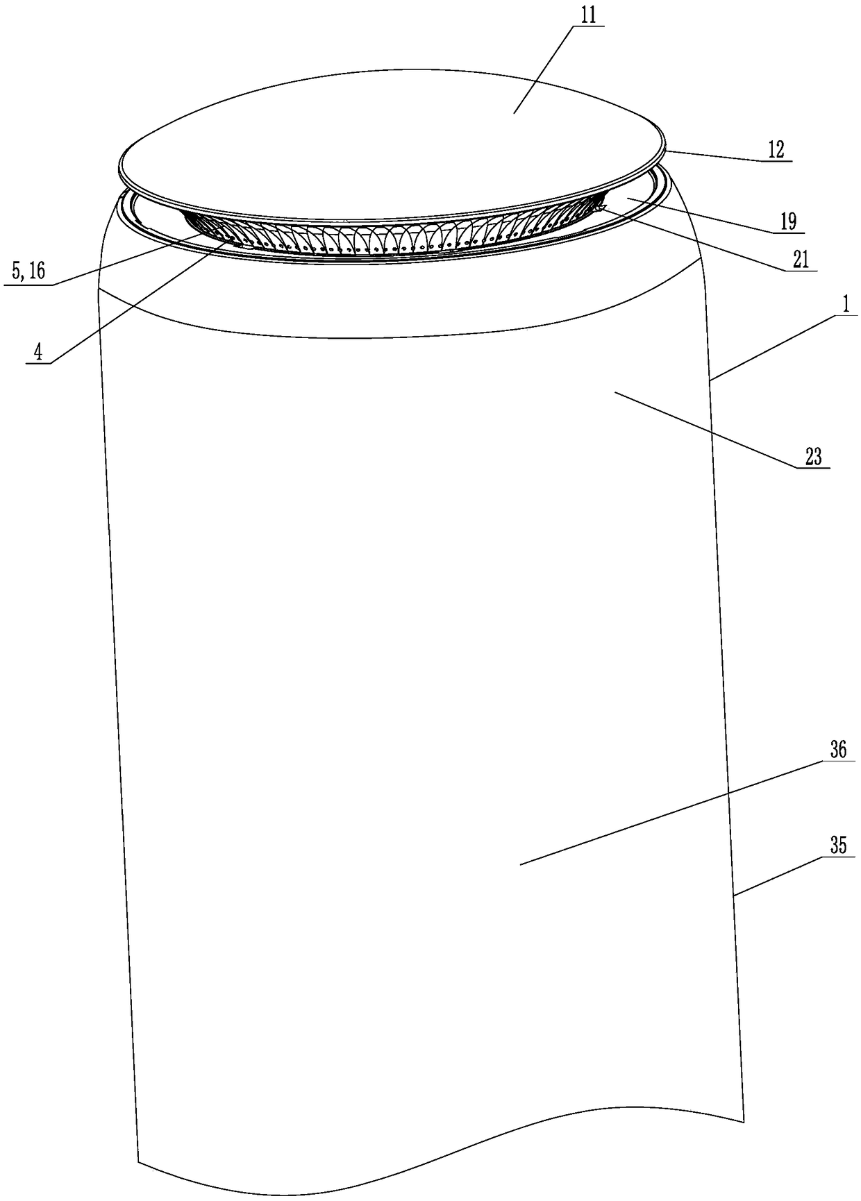
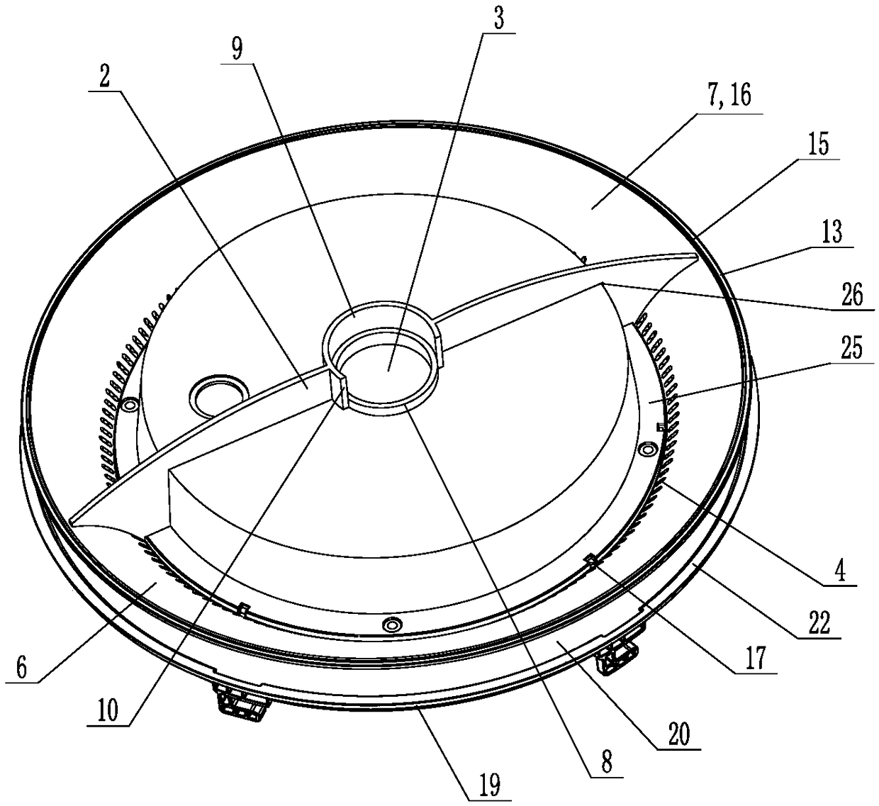
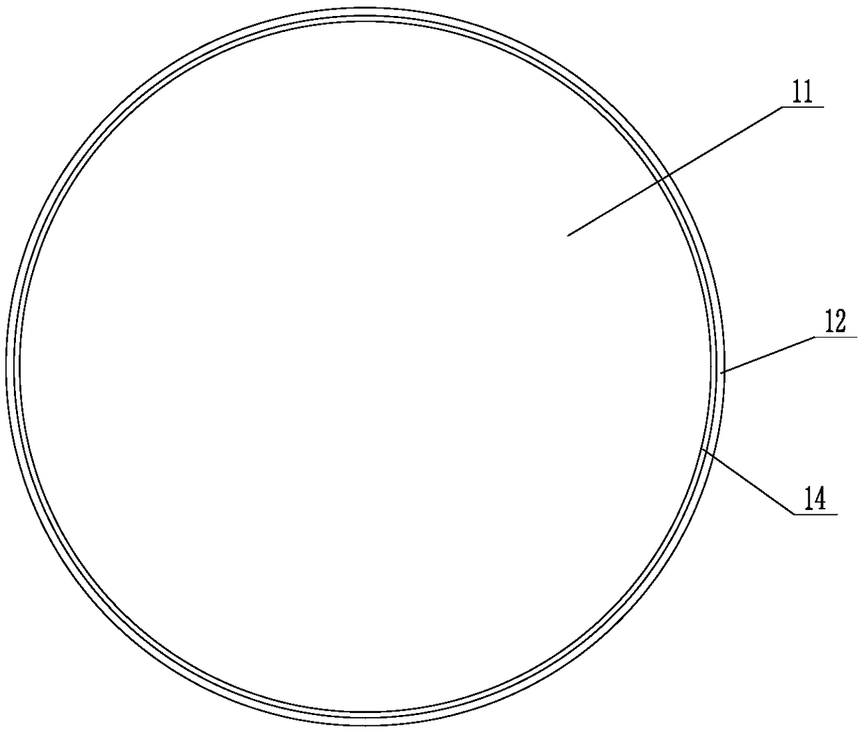
[0065] Such as Figure 1 to Figure 5 , Figure 9 As shown, the humidifier of the present invention includes a body 1 and a fog shield 2. The body 1 is provided with a cavity, a mist inlet hole 3 and a plurality of mist outlet holes 4, and the mist inlet hole 3 and the plurality of mist outlet holes 4 are all connected to The cavities are connected, and a plurality of mist outlet holes 4 are arranged at circumferential intervals on the side wall of the cavity, and the outer surface of the cavity side wall above the mist outlet holes 4 is provided with an upper guide surface that gradually slopes outward from bottom to top 5. The fog shield 2 is located in the cavity and is detachably connected to the body 1. The fog shield 2 divides the cavity into two parts: the mist outlet chamber 6 and the isolation chamber 7. At least one mist outlet hole 4 is connected to the mist outlet chamber. 6, at least one mist outlet hole 4 communicates with the isolation chamber 7, and the mist in...

Embodiment 2

[0090] The difference between this embodiment and embodiment 1 is that the structure of the fog shield 2 adopted is different, specifically:

[0091] Such as figure 1 , image 3 , Figure 6 to Figure 9 As shown, the fog shield 2 includes a first half plate 27 and a second half plate 28, and the first half plate 27 and the second half plate 28 can perform relative rotation in the cavity with the central axis of the cavity as the rotation axis. .

[0092] The lower wall of the cavity is provided with an annular boss 8, the annular boss 8 is arranged coaxially with the cavity, the mist inlet hole 3 is arranged on the lower wall of the cavity inside the annular boss 8, and the lower part of one end of the first half plate 27 An annular connecting ring 9 is provided, the inner peripheral wall of the connecting ring is cylindrical, the connecting ring 9 is sleeved on the annular boss 8, and the inner peripheral wall of the connecting ring 9 is interference fit with the outer peri...

Embodiment 3

[0098] Such as Figure 1 to Figure 9 As shown, the split-type air conditioner of the present invention includes a floor-standing indoor unit 35 and the humidifier in Embodiment 1 or 2, and the humidifier is arranged on the top of the floor-standing indoor unit 35. In this embodiment, the floor-standing indoor unit 35 includes The shell 36, the shell 23 of the humidifier is located above the shell 36, and the shell 23 of the humidifier is integrated with the shell 36.


PUM


Abstract

The invention relates to a humidifier, and further relates to a split air conditioner. The humidifier comprises a body and a fog blocking plate, wherein a cavity, a fog inlet and a plurality of fog outlets are formed in the body; the fog inlet and the plurality of fog outlets communicate with the cavity; the plurality of fog outlets are formed in the side wall of the cavity in the circumferentialdirection at intervals; an upper guide surface which gradually inclines outwards from bottom to up is arranged in the position, above the fog outlets, on the outer side surface of the side wall of thecavity; the fog blocking plate is positioned in the cavity and is detachably connected with the body; the fog blocking plate divides the cavity into a fog outlet cavity and an isolation cavity; at least one fog outlet communicates with the fog outlet cavity; at least one fog outlet communicates with the isolation cavity; and the fog inlet communicates with the fog outlet cavity. The split air conditioner comprises a floor type indoor unit and the humidifier, wherein the humidifier is arranged at the top of the floor type indoor unit. The humidifier has the advantages that the problems that water is accumulated and dust enters the fog outlets can be effectively solved, the humidifier can be healthily and sanitarily utilized for a long time, besides, the fog outlet range can be adjusted, the requirement on the placing position is relatively low, and applicability is high.

Description

technical field [0001] The invention relates to an air humidifying device, in particular to a humidifier and a split air conditioner. Background technique [0002] Air humidity is one of the important factors that affect the comfort of the environment, especially in northern regions and places where split air conditioners are often used. Therefore, humidifiers that increase ambient humidity have increasingly become essential small appliances for many families. Humidifiers usually use a fan to directly suck in the air, and then let the air blow out together with the water mist after ultrasonic vibration to form a humidified air. At present, most of the humidifiers on the market have their mist outlets located above the humidifier, and in order to achieve humidification in all directions of the room, a circumferential mist outlet structure has been adopted, which has the following problems: 1. The top of the humidifier is easy to accumulate Water will cause the growth of harm...

Claims


Application Information

Patent Timeline
Patent Type & Authority Applications(China)
IPC IPC(8): F24F1/00F24F6/12F24F13/00
CPCF24F1/0007F24F6/12F24F13/00Y02B30/70
Inventor 王松古汤汤陈伟李松许壮孙品品竺熔秦立振黄涛吴庆壮邹波罗会斌杜建刘卫平
Owner AUX AIR CONDITIONING LTD BY SHARE LTD
Learn More