Leather surface cleaning brushing device for leather product production
A technology for leather products and leather, applied in the field of leather surface scrubbing devices for leather product production, can solve the problems of inability to meet the needs of leather production and processing, low efficiency, unsatisfactory cleaning effect, etc., to improve the cleaning range, increase cleaning efficiency, and adjust strong effect
- Summary
- Abstract
- Description
- Claims
- Application Information
AI Technical Summary
Problems solved by technology
Method used
Image
Examples
Embodiment 1
[0023] see Figure 1-5 , a leather surface scrubbing device for leather product production, comprising a base plate 1, a frame 8, a drive motor 2 and a water tank 13 are fixedly installed on the base plate 1, the water tank 13 provided is used to store clean water for cleaning leather, and the drive motor 2 A drive shaft 33 is coaxially and fixedly installed on the output shaft, and a driving pulley 3 is sleeved and fixedly installed on the drive shaft 33. A driven shaft 6 is provided on the frame 8 in a rotating manner, and a slave shaft 6 is sleeved and fixedly installed on the surface of the driven shaft 6. The driving pulley 5, the driven pulley 5 and the driving pulley 3 are sheathed and connected with a transmission belt 23.
[0024] The driving motor 2 can drive the driving shaft 33 to rotate, and the driving shaft 33 drives the driving pulley 3 to rotate, and the driving pulley 3 drives the driven pulley 5 to rotate through the transmission belt 23 . The right end of ...
Embodiment 2
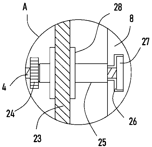
[0028] On the basis of Embodiment 1, in addition, a T-shaped slot 26 is provided on the side wall of the frame 8, and a limit block 27 is slidably embedded in the T-shaped slot 26, and a threaded rod 4 is fixedly installed on the limit block 27, and the threaded rod 4 is A movable sleeve 25 is sleeved, and the surface of the movable sleeve 25 is connected with an adjustment pulley 28 through a bearing. The adjustment pulley 28 is connected with the transmission belt 23, and the side wall of the frame 8 is longitudinally provided with a strip hole 9, and the driven shaft 6 The adjustment sleeve 10 passing through the strip hole 9 is sleeved on the auxiliary pipe 34 , and the adjustment spring 7 fixed between the adjustment sleeve 10 and the frame 8 is arranged in the strip hole 9 .
[0029] Further, a running wheel 24 is threadedly connected to the threaded rod 4 , and the running wheel 24 is pressed against the left end surface of the movable sleeve 25 on the side close to the ...
Embodiment 3
[0034] On the basis of Embodiment 2, in addition, a transmission gear 32 is sheathed and fixed on the rotating shaft 21 , and a spur rack 18 meshing with the transmission gear 32 is fixedly installed on the left side wall of the bearing plate 11 .
[0035] Further, the bottom plate 1 is rotatably provided with a rotating shaft 21, the rotating shaft 21 is sheathed and fixed with a bevel gear I19 and a bevel gear II20, and the right end of the driving shaft 33 is coaxially fixedly installed with a bevel gear I19 or a bevel gear II20 meshingly connected. Incomplete bevel gear 22.
[0036] Furthermore, two parallel guide grooves 15 are provided on the support plate 17 , and two guide legs 16 slidably embedded in the guide grooves 15 are vertically and fixedly installed on the bottom of the bearing plate 11 .
[0037]The driving motor 2 drives the drive shaft 33 to rotate, and the drive shaft 33 drives the incomplete bevel gear 22 fixedly connected with it to rotate clockwise. Whe...
PUM
 Abstract
Description
Claims
Application Information
 - R&D Engineer
- R&D Manager
- IP Professional
- Industry Leading Data Capabilities
- Powerful AI technology
- Patent DNA Extraction
Browse by: Latest US Patents, China's latest patents, Technical Efficacy Thesaurus, Application Domain, Technology Topic, Popular Technical Reports.
© 2024 PatSnap. All rights reserved.Legal|Privacy policy|Modern Slavery Act Transparency Statement|Sitemap|About US| Contact US: help@patsnap.com


