
Tire retreading equipment

A tire retreading and equipment technology, applied in metal processing equipment, grinding/polishing equipment, tires, etc., can solve the problems of difficult tread grinding, reduction of carcass thickness, low grinding efficiency, etc., to achieve high grinding efficiency and safety. High performance and the effect of ensuring overall quality

Active Publication Date: 2018-11-30
ZHEJIANG IND POLYTECHNIC COLLEGE
View PDF5 Cites 0 Cited by
  • Summary
  • Abstract
  • Description
  • Claims
  • Application Information

AI Technical Summary

Problems solved by technology

[0002] In the tire retreading process, grinding is a very important process. Its purpose is to grind off the tire surface pattern and grind it into a tread with uniform roughness, which is convenient for replacing the tire with a new tread. The quality of grinding will directly affect the The quality of retreaded tires; the existing grinding machine usually uses a motor to drive the grinding head to rotate at a high speed, so that the tread can be quickly wiped off; The machine and the tread are in hard contact. During the grinding process, the mechanical arm drives the grinding piece to move downward, and the mechanical arm exerts downward pressure on the grinding piece. After grinding a layer during the grinding process, the mechanical arm needs to drive the grinding piece Move down once, and then re-grind one layer. Therefore, it is necessary to continuously drive the grinding piece to move downward during grinding, and the grinding efficiency is low; It is easy to grind off a layer of carcass under the tread due to the excessive pressure of the mechanical arm, resulting in a reduction in the thickness of the carcass, resulting in safety hazards such as tire blowouts after retreading

Method used


Image

  • Tire retreading equipment
  • Tire retreading equipment
  • Tire retreading equipment

Examples


Embodiment Construction

[0024] In order to enable those skilled in the art to better understand the solutions of the present invention, the technical solutions in the embodiments of the present invention will be clearly and completely described below in conjunction with the drawings in the embodiments of the present invention.

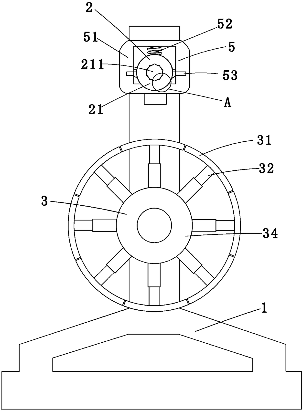
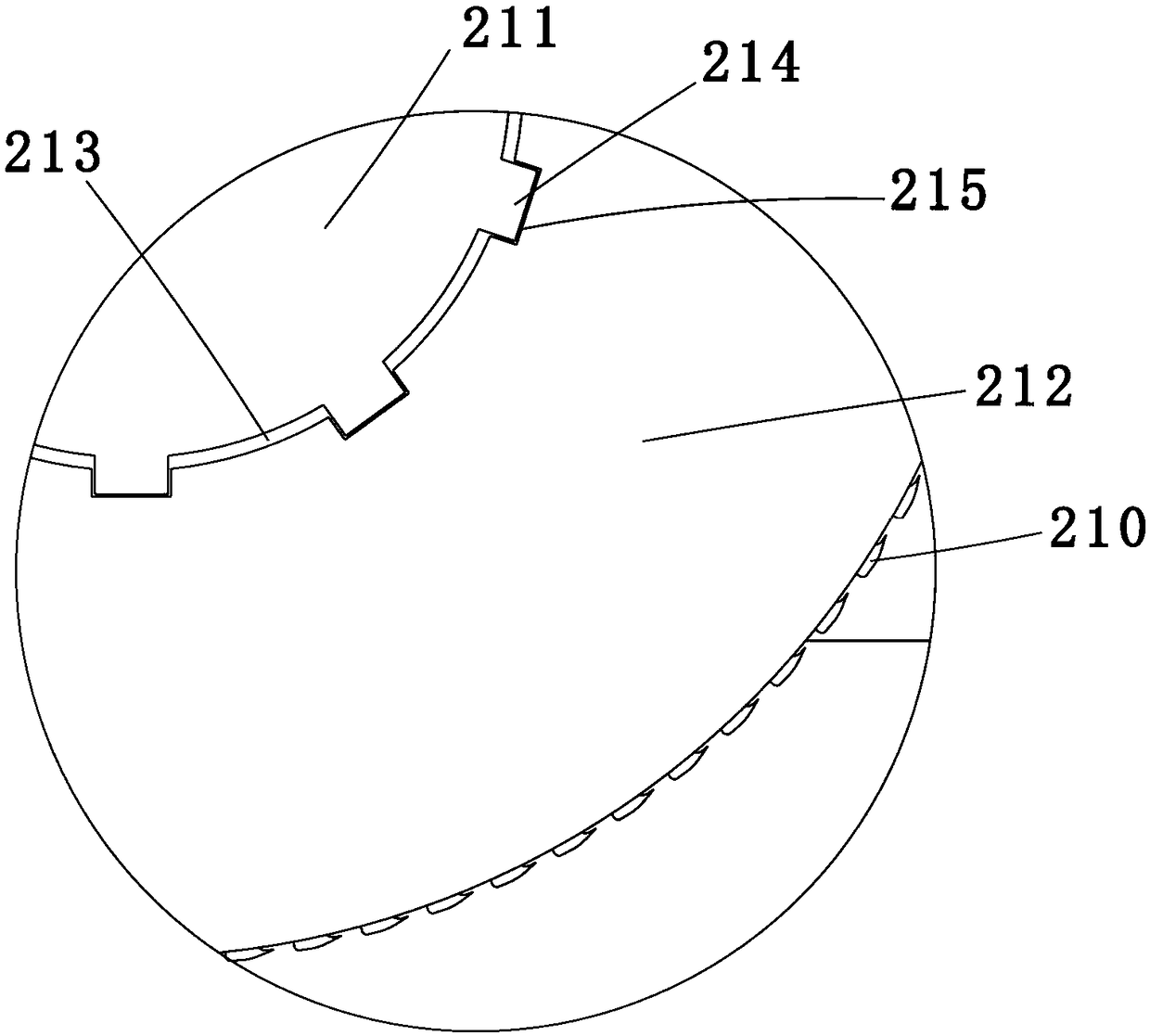
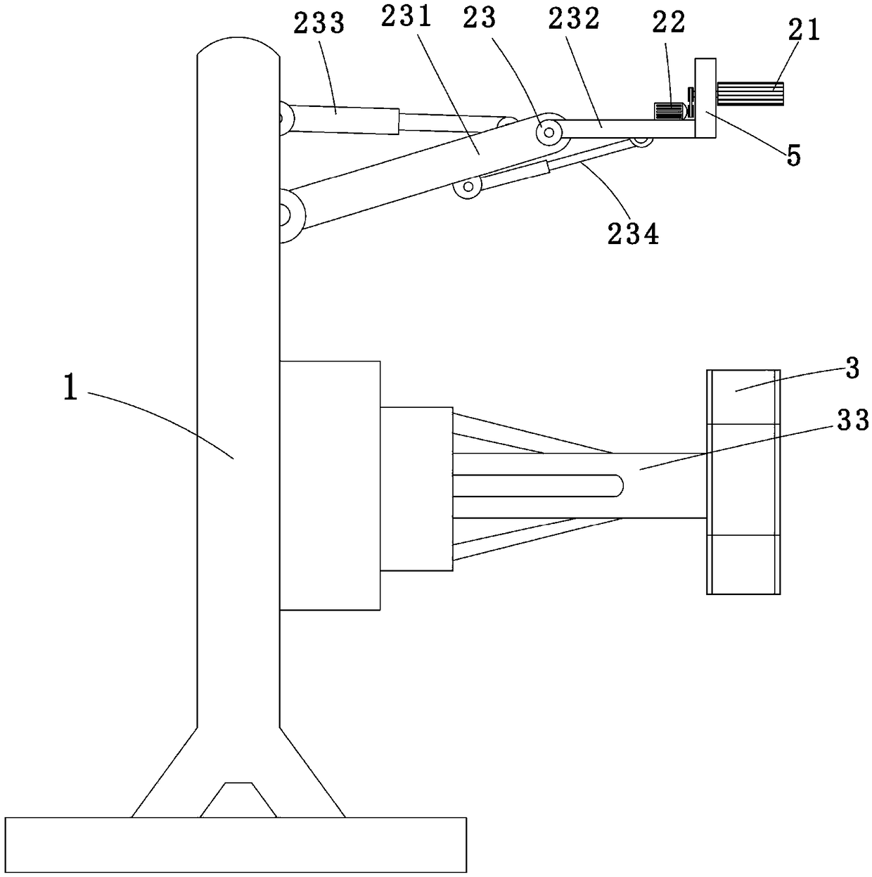
[0025] Such as Figure 1-10 As shown, a tire retreading equipment includes a frame body 1, a grinding device 2 and a fixing device 3, wherein the frame body 1 is a metal frame; the fixing device 3 includes a plurality of fixing pieces 31, a driving cylinder 32 and a main rod 33. The fixed piece 31 is an arc-shaped metal sheet; a plurality of fixed pieces 31 form a metal ring; the driving cylinder 32 is an existing cylinder on the market; the main rod 33 is a metal rod, and the main rod 33 is a metal rod. One end of the rod 33 is connected with the frame body 1 , and the other end is connected with a connecting piece 34 by bolts, the connecting piece 34 is a thicker metal disc...


PUM


Abstract

The invention discloses tire retreading equipment which comprises a frame, a polishing device and a fixing device. The polishing device and the fixing device are arranged on the frame, the polishing device comprises a polishing member, a driving member for driving the polishing member to rotate and a mechanical arm for driving the polishing member to move up and down, the driving member is arranged on the mechanical arm which is connected with the polishing member through a connection structure, and the polishing member can float up and down on the connection structure. By arranging the connection structure, the polishing member can float up and down, contacts with a tread and automatically moves downwards, so that tire polishing efficiency is high; a tire body is ensured to be unchanged in thickness, and the whole tire is ensured to be unchanged in quality and high in safety.

Description

technical field [0001] The invention belongs to the technical field of tire retreading, in particular to tire retreading equipment. Background technique [0002] In the tire retreading process, grinding is a very important process. Its purpose is to grind off the surface pattern of the tire and grind it into a tread with uniform roughness, which is convenient for replacing the tire with a new tread. The quality of grinding will directly affect the The quality of retreaded tires; the existing grinding machine usually uses a motor to drive the grinding head to rotate at a high speed, so that the tread can be quickly wiped off; The machine and the tread are in hard contact. During the grinding process, the mechanical arm drives the grinding piece to move downward, and the mechanical arm exerts downward pressure on the grinding piece. After grinding a layer during the grinding process, the mechanical arm needs to drive the grinding piece Move down once, and then re-grind one la...

Claims


Application Information

Patent Timeline
Patent Type & Authority Applications(China)
IPC IPC(8): B24B5/36B29D30/54
CPCB24B5/35B24B5/366B24B5/50B29D30/54B29D2030/541
Inventor 李小红王建伟
Owner ZHEJIANG IND POLYTECHNIC COLLEGE
Learn More