
Wood door perforation cooling device

A technology of cooling device and wooden door, which is applied in the direction of wood processing equipment, metal processing machinery parts, maintenance and safety accessories, etc., can solve the problems of poor workshop environment, poor workshop environment, overheating and fracture of drill bits, etc., and achieve good cooling effect and reduce Maintenance frequency, the effect of low maintenance frequency

Inactive Publication Date: 2018-11-30
湖州欧贝得门业有限公司
View PDF0 Cites 0 Cited by
  • Summary
  • Abstract
  • Description
  • Claims
  • Application Information

AI Technical Summary

Problems solved by technology

For high-hardness wooden doors, that is, wooden doors made with high-hardness wood as raw materials, such as ebony, rosewood and chicken wing wood, in the drilling process, due to the drill bit and high-hardness wood Severe friction can easily cause the drill head to heat up. Nowadays, most wooden door manufacturers use automatic equipment to drill holes. The drilling frequency is very fast. It is especially easy to break due to overheating. If the drill bit breaks in high-hardness wood, the wood will be scrapped, and most high-hardness woods are more expensive, so the possibility of drill bit breakage must be reduced, so when drilling high-hardness wood. Cool the drill bit
The existing drill bit cooling method is usually air cooling, that is, compressed air is used to directly blow the drill bit, but the air cooling will blow up a large amount of sawdust generated by the drill bit, resulting in a poor workshop environment
Therefore, the use of air cooling to cool the drill bit has the disadvantage of causing a poor workshop environment

Method used


Image

  • Wood door perforation cooling device

Examples


Embodiment Construction

[0012] The present invention will be further described below in conjunction with the accompanying drawings and embodiments, but not as a basis for limiting the present invention.

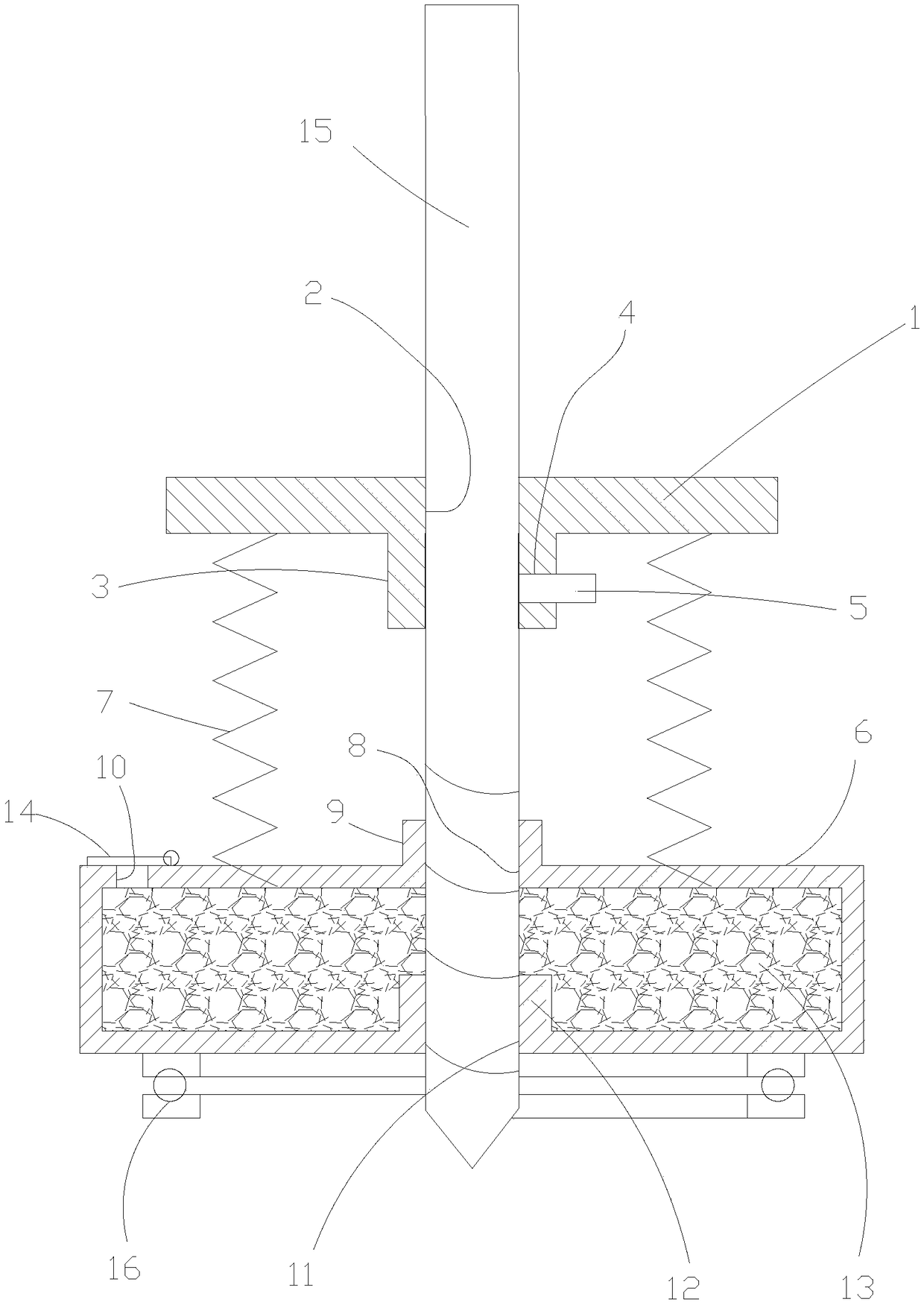
[0013] Example. A wooden door perforating cooling device, comprising a circular fixing plate 1, the fixing plate 1 is provided with a first through hole 2 in the axial direction, the edge of the first through hole 2 is provided with a downward first flange 3, the second The side wall of a flanging 3 is provided with a threaded hole 4, and a screw 5 is arranged in the threaded hole 4, and a cooling box 6 is provided under the fixed plate 1, and the fixed plate 1 is connected with the cooling box 6 by a spring 7, and the cooling box 6 The top plate is provided with a second through hole 8 coaxial with the first through hole 2, and the edge of the second through hole 8 is provided with an upward second flange 9, and one side of the second flange 9 is provided with a water inlet hole 10. The bottom pla...


PUM


Abstract

The invention discloses a wood door perforation cooling device. The device comprises a circular fixing plate. A first through hole is formed in the fixing plate in the axial direction. A first downward turnup is arranged at the edge of the first through hole. A threaded hole is formed in the side wall of the first turnup. A screw is arranged in the threaded hole. A cooling box is arranged below the fixing plate. The fixing plate is connected with the cooling box through springs. A second through hole coaxial with the first through hole is formed in a top plate of the cooling box. A second upward turnup is arranged at the edge of the second through hole. A water inlet is formed in one side of the second turnup. A third through hole coaxial with the first through hole is formed in a bottom plate of the cooling box. A third upward turnup is arranged at the edge of the third through hole. Humid absorbent cotton is arranged inside the cooling box. Surface bearings are arranged at the bottoms of the cooling box. By adopting a cooling drill bit provided by the invention, the advantage that a workshop environment is not worsened is achieved, the cooling effect is good, and the maintenancefrequency is low.

Description

technical field [0001] The invention belongs to the field of punching equipment for wooden doors, and in particular relates to a cooling device for punching holes in wooden doors. Background technique [0002] Wooden doors are made of wood as raw material, and there are multiple processes of punching wood in the manufacturing process of wooden doors. For high-hardness wooden doors, that is, wooden doors made with high-hardness wood as raw materials, such as ebony, rosewood and chicken wing wood, in the drilling process, due to the drill bit and high-hardness wood Severe friction can easily cause the drill head to heat up. Nowadays, most wooden door manufacturers use automatic equipment to drill holes. The drilling frequency is very fast. It is especially easy to break due to overheating. If the drill bit breaks in high-hardness wood, the wood will be scrapped, and most high-hardness woods are more expensive, so the possibility of drill bit breakage must be reduced, so when ...

Claims


Application Information

Patent Timeline
Patent Type & Authority Applications(China)
IPC IPC(8): B23Q11/10B27C3/00
CPCB23Q11/10B27C3/00
Inventor 钱利中
Owner 湖州欧贝得门业有限公司
Learn More