Pipe clamping mechanism

A clamping mechanism and pipe technology, applied in metal processing equipment, feeding devices, manufacturing tools, etc., can solve problems such as waste of materials and deformation, and achieve the effect of saving costs and increasing service life.

Inactive Publication Date: 2018-11-30
朱婷婷
View PDF3 Cites 1 Cited by
  • Summary
  • Abstract
  • Description
  • Claims
  • Application Information

AI Technical Summary

Problems solved by technology

In the existing straightening machine, when the pipe is clamped, the clamped part of the pipe is often deformed, and the deformed part needs to be sawed off after subsequent straightening, which wastes material

Method used


Image

  • Pipe clamping mechanism
  • Pipe clamping mechanism
  • Pipe clamping mechanism

Examples


Embodiment Construction

[0019] The present invention will be further described below in combination with specific embodiments. Wherein, the accompanying drawings are only for illustrative purposes, showing only schematic diagrams, rather than physical drawings, and should not be construed as limitations on this patent; in order to better illustrate the embodiments of the present invention, some parts of the accompanying drawings will be omitted, Enlargement or reduction does not represent the size of the actual product; for those skilled in the art, it is understandable that certain known structures and their descriptions in the drawings may be omitted.

[0020] In the drawings of the embodiments of the present invention, the same or similar symbols correspond to the same or similar components; The orientation or positional relationship indicated by etc. is based on the orientation or positional relationship shown in the drawings, which is only for the convenience of describing the present invention ...


PUM


Abstract

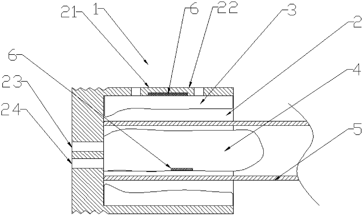
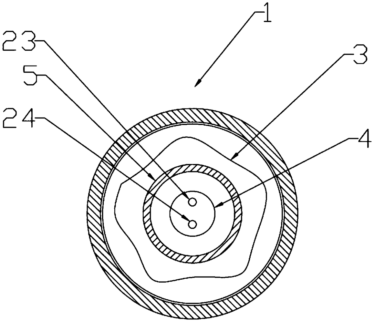
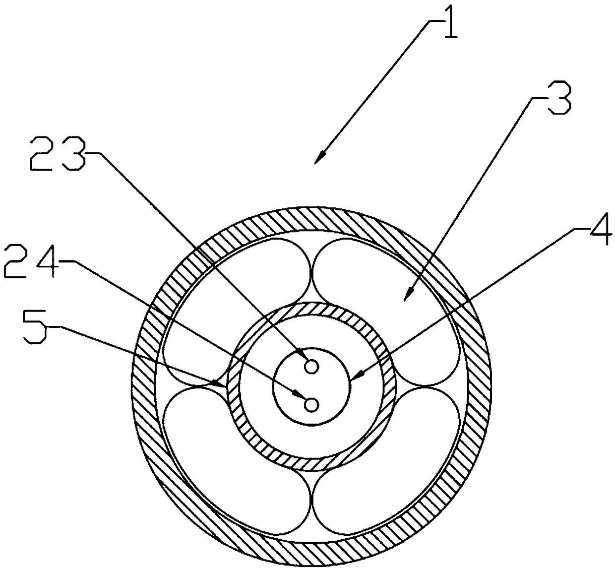
The invention relates to the technical field of pipe production equipment and provides a pipe clamping mechanism. The pipe clamping mechanism comprises a clamping mechanism body and a mounting groovein the clamping mechanism body, and an inflation part is arranged in the mounting groove and at least abutted against the inner surface or the outer surface of a pipe. The pipe clamping mechanism hasadvantages that pipe clamping force can be guaranteed without any adverse influences on pipe surfaces, and pipe quality is guaranteed.

Description

technical field [0001] The invention relates to the technical field of pipe production equipment, in particular to a pipe clamping mechanism. Background technique [0002] Pipes tend to be twisted to varying degrees during production and processing, resulting in bending, so the straightening machine is a machine that is frequently used in aluminum profile processing. In the existing straightening machine, when the pipe is clamped, the clamped part of the pipe is often deformed, and the deformed part needs to be sawed off after subsequent straightening, which wastes material. Contents of the invention [0003] The invention provides a pipe clamping mechanism aiming at the deficiencies of the prior art, which can ensure the clamping strength of the pipe without any adverse effect on the surface of the pipe and ensure the quality of the pipe. [0004] The invention provides a pipe clamping mechanism, which includes a clamping mechanism body and a mounting groove provided on ...

Claims


Application Information

Patent Timeline
Patent Type & Authority Applications(China)
IPC IPC(8): B21D43/00
CPCB21D43/003
Inventor 朱婷婷
Owner 朱婷婷
Why Eureka
Try Eureka