
Heat exchange tube reaming device

A technology of heat exchange tubes and hole heads, which is applied in the field of heat exchange tube reaming devices, can solve the problems of heat exchange tubes relying on manpower, etc., and achieve the effects of reduced production costs, low failure rate, and convenient operation

Pending Publication Date: 2018-11-30
四川凯润电器有限公司
View PDF13 Cites 2 Cited by
  • Summary
  • Abstract
  • Description
  • Claims
  • Application Information

AI Technical Summary

Problems solved by technology

[0003] The object of the present invention provides a heat exchange tube reaming device, which solves the problem in the prior art that heat exchange tubes are reamed by manpower

Method used


Image

  • Heat exchange tube reaming device
  • Heat exchange tube reaming device
  • Heat exchange tube reaming device

Examples


Embodiment 1

[0032] This embodiment provides a heat exchange tube expansion device, such as Figure 1 to Figure 7 shown.

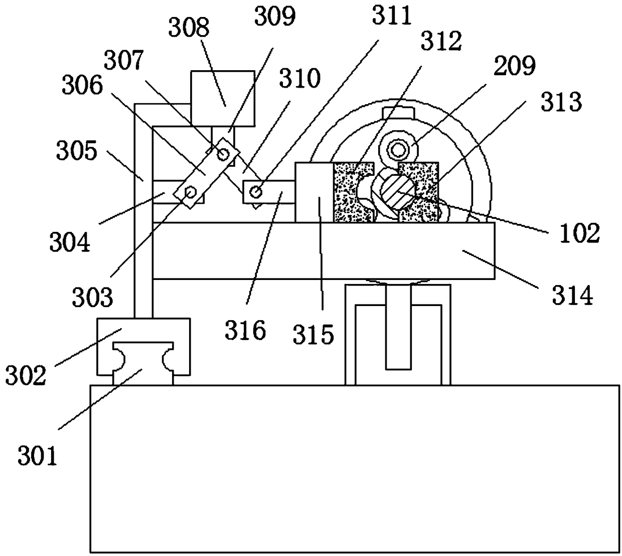
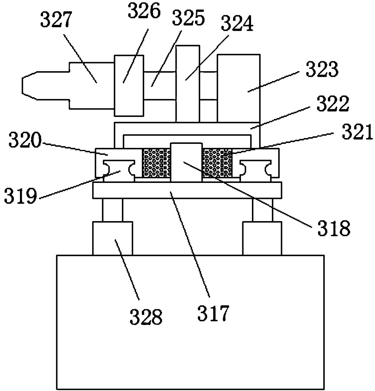
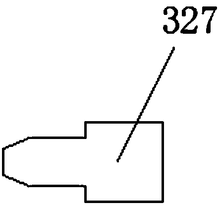
[0033] A heat exchange tube reaming device, including a reaming mechanism, a fixing mechanism for fixing the heat exchange tube 102 during reaming, and a transfer mechanism for transferring the heat exchange tube 102 to the next process after reaming, the reaming mechanism Including hydraulic cylinder six 323, the output end of hydraulic cylinder six 323 is connected with the reaming shaft 325, the end of the reaming shaft 325 is provided with a reaming head fixing seat 326, and the end of the reaming head fixing seat 326 is fixedly provided with a reaming Head one 327 and reaming head two 339, reaming head one 327 and reaming head two 339 are arranged in parallel.

Embodiment 2

[0035] This embodiment provides a heat exchange tube expansion device, such as Figure 1 to Figure 7 shown.

[0036]A heat exchange tube reaming device, including a reaming mechanism, a fixing mechanism for fixing the heat exchange tube 102 during reaming, and a transfer mechanism for transferring the heat exchange tube 102 to the next process after reaming, the reaming mechanism Including hydraulic cylinder six 323, the output end of hydraulic cylinder six 323 is connected with the reaming shaft 325, the end of the reaming shaft 325 is provided with a reaming head fixing seat 326, and the end of the reaming head fixing seat 326 is fixedly provided with a reaming Head one 327 and reaming head two 339, reaming head one 327 and reaming head two 339 are arranged in parallel.

[0037] The hydraulic cylinder six 323 is arranged on the support platform two 322, the support platform two 322 is arranged on the slide block three 320, the slide block three 320 is arranged on the guide ...

Embodiment 3

[0039] This embodiment provides a heat exchange tube expansion device, such as Figure 1 to Figure 7 shown.

[0040] A heat exchange tube reaming device, including a reaming mechanism, a fixing mechanism for fixing the heat exchange tube 102 during reaming, and a transfer mechanism for transferring the heat exchange tube 102 to the next process after reaming, the reaming mechanism Including hydraulic cylinder six 323, the output end of hydraulic cylinder six 323 is connected with the reaming shaft 325, the end of the reaming shaft 325 is provided with a reaming head fixing seat 326, and the end of the reaming head fixing seat 326 is fixedly provided with a reaming Head one 327 and reaming head two 339, reaming head one 327 and reaming head two 339 are arranged in parallel.

[0041] The hydraulic cylinder six 323 is arranged on the support platform two 322, the support platform two 322 is arranged on the slide block three 320, the slide block three 320 is arranged on the guide...


PUM


Abstract

The invention relates to the technical field of pipeline processing, in particular to a heat exchange tube reaming device. The heat exchange tube reaming device comprises a reaming mechanism, a fixingmechanism and a transporting mechanism, wherein a heat exchange tube is fixed through the fixing mechanism during reaming, and is transported for the next working operation through the transporting mechanism after reaming. The reaming mechanism comprises a sixth hydraulic cylinder. The output end of the sixth hydraulic cylinder is connected with a reaming shaft. A reaming head fixing base is arranged on the end portion of the reaming shaft. A first reaming head and a second reaming head are fixedly arranged on the end portion of the reaming head and are parallel to each other. The heat exchange tube reaming device is simple in structure, convenient to operate and low in failure rate. The heat exchange tube to be reamed is fixed through the fixing mechanism at first, and then a reamer is used for reaming. After reaming is completed, the fixing mechanism is unfolded to release the heat exchange tube, and the heat exchange tube is clamped and transported to the next working position by the transporting mechanism. The whole process is completed fully automatically without manual operation, and therefore the production efficiency, finished product rate and reaming speed are high, and production cost is reduced.

Description

technical field [0001] The invention relates to the technical field of pipeline processing, in particular to a heat exchange tube reaming device. Background technique [0002] In products such as water heaters, the heat exchange tube wound outside the heating chamber is an essential part. When the heat exchange tube leaves the factory, it is wound on the drum for the convenience of transportation. When it needs to be processed according to the structure required by the water heater, the heat exchange tube needs to be straightened first, and then cut to the predetermined length. The end surface needs to be reamed to facilitate connection with the supporting pipes. Existing manufacturers still use manpower to ream the holes, which is extremely inefficient, and the reaming depths are not uniform, resulting in high scrap rates. Contents of the invention [0003] The object of the present invention is to provide a heat exchange tube reaming device, which solves the problem in ...

Claims


Application Information

Patent Timeline
Patent Type & Authority Applications(China)
IPC IPC(8): B21D41/02B21D43/00B21D45/02B21D53/02
CPCB21D41/02B21D43/003B21D45/02B21D53/02
Inventor 吕小军叶跃武
Owner 四川凯润电器有限公司
Learn More