Mains voltage leakage detection control circuit and method

A leakage detection and control circuit technology, applied in the field of lighting, can solve problems such as inconvenient replacement or replacement of lamps, damp circuit boards, electric shock hazards, etc., and achieve the effects of simple and reliable peripherals, strong reliability, and system cost savings

Active Publication Date: 2020-08-04
QX MICRO DEVICES
View PDF7 Cites 0 Cited by
  • Summary
  • Abstract
  • Description
  • Claims
  • Application Information

AI Technical Summary

Problems solved by technology

2. Even if there is no problem with the circuit board itself of the electrical appliance, the phenomenon of leakage will occur due to the leakage of some components (especially the capacitor) or because the circuit board is damp and dusty. It is not charged, but it is charged again after using it for a period of time. This is mostly the case
However, there will be a situation that when the LED lighting module is installed or other accidents occur, one end of the lighting module has been connected to the live wire L of the mains. If the human body accidentally touches the The other end of the LED lamp module will input the live wire to the ground, which is equivalent to the series connection of two impedances. When the impedance of the human body is the same order of magnitude or close to the impedance of the lamp, the current of the mains voltage will pass through When the lamp passes through the human body and then reaches the ground, a large voltage will be formed on the impedance of the human body, which will cause the human body to receive electric shock and cause electric shock danger
[0004] The technical characteristics and disadvantages of the traditional technology are: when ordinary LED lamp modules replace fluorescent lamps, there is a risk of electric shock during installation or abnormal use, so professional technical installers are required to replace the module and replace the lamps. Replacement or replacement has caused great inconvenience and danger, and inhibited the widespread promotion of environmentally friendly and energy-saving LED lamps

Method used


Image

  • Mains voltage leakage detection control circuit and method
  • Mains voltage leakage detection control circuit and method
  • Mains voltage leakage detection control circuit and method

Examples


Embodiment Construction

[0022] In order to make the object, technical solution and advantages of the present invention clearer, the present invention will be further described in detail below in conjunction with the accompanying drawings and embodiments. It should be understood that the specific embodiments described here are only used to explain the present invention, not to limit the present invention.

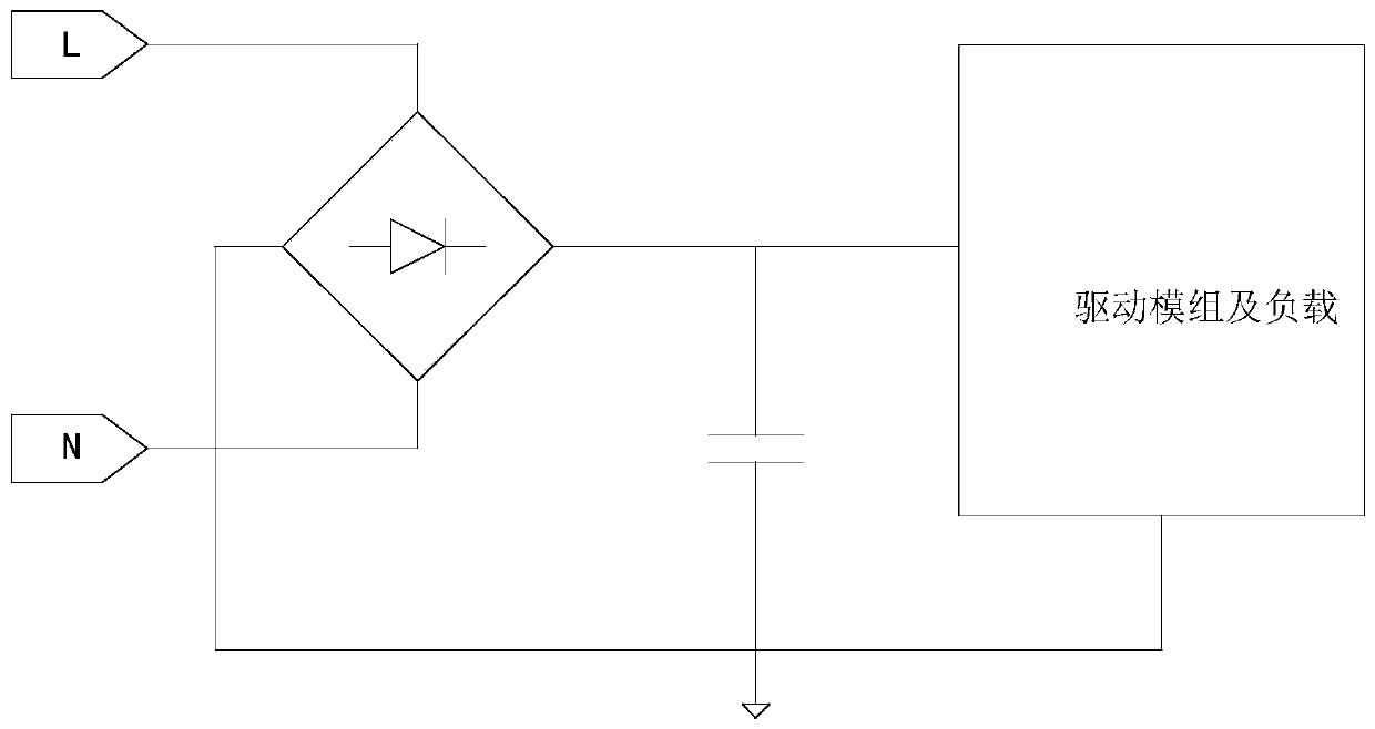
[0023] see figure 1 As shown, in the prior art, this circuit is based on the principle of an ordinary LED lamp module. This module receives an AC voltage input from the live line L and neutral line N of the mains, passes through a rectifier bridge and passes through a filter capacitor to obtain a DC voltage, and then for The drive module and the load supply power to make the drive module work normally and make the load LED achieve the expected setting effect.

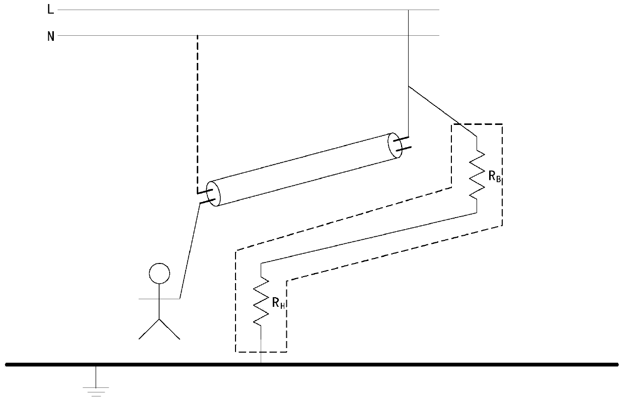
[0024] see figure 2 As shown, in the process of replacing the fluorescent lamp with an ordinary LED lamp module, one end of the lamp nee...


PUM


Abstract

The invention discloses a mains voltage leakage detection control circuit and method. The circuit includes a detection protection chip, and the VAC pin in the chip is connected to the VSS pin through the chip resistance R1 and the chip resistance R2; the VAC pin is detected through the online ICT Connect to VSS; between the chip resistor R1 and the chip resistor R2 connect the negative pole of the comparator CPA, the positive pole of the comparator CPA is connected to REF, the output terminal of the comparator is connected to the logic control circuit; the GND pin is connected to the source of the control switch MOS transistor Q1 , the SW pin is connected to the drain of the control switch MOS transistor Q1, and the gate of the control switch MOS transistor Q1 is connected to the logic control circuit. Compared with the prior art, in the present invention, the mains voltage leakage detection control circuit, its detection and protection chip controls the turn-off of the control switch MOS transistor Q1, controls the voltage within the range that the human body can bear, and protects the human body from electric shock .

Description

technical field [0001] The invention belongs to the field of lighting, and in particular relates to a mains voltage leakage detection control circuit and method. Background technique [0002] Leakage is caused by a certain potential difference between the electrical casing and the live wire of the mains for some reason and the ground. There are two reasons for the leakage: 1. The circuit board used by some electrical appliances has its own problems (the low-voltage circuit of the circuit board is not isolated from the 220V AC, and it itself has mains power), and most of the electrical appliances using switching power supply belong to this situation. . For example, some old-fashioned color TVs will feel numb when people touch the antenna. This is the leakage caused by the connection between the antenna and the circuit board. However, these electricity are not very dangerous to people, because there is a resistor with a large resistance between the circuit board and the main...

Claims


Application Information

Patent Timeline
Patent Type & Authority Patents(China)
IPC IPC(8): H05B45/50H05B44/00
CPCH05B45/50H05B45/37Y02B20/30
Inventor 黄朝刚李剑
Owner QX MICRO DEVICES
Why Eureka
Try Eureka