


Quick Research
Generate reliable direction feasibility study reports for your R&D in just a few steps.

Technical Q&A
Discover and master advanced knowledge NOW. Basics, ideas, possibilities, all at once.

Find Solutions
As an expert in R&D theories, this can generate solutions to your technical problems instantly.

Evaluate Feasibility
Analyze your overall solution with one click, know your potential R&D risks in advance.

Monitor Landscape
Get weekly tech updates, stay abreast of the latest tech innovations and key insights.
Resonance circuit -based charged ice melting topology system and ice melting method thereof
A resonant circuit and ice-melting technology, which is applied in the installation of cables, electrical components, overhead lines/cable equipment, etc., can solve the problems of high line structure requirements, narrow application range, and large system consumption, so as to improve the anti-icing ability , Ease of design, and the effect of reducing device loss
- Summary
- Abstract
- Description
- Claims
- Application Information
AI Technical Summary
Problems solved by technology
Method used
Image

Examples
Embodiment 1
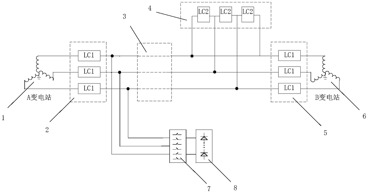
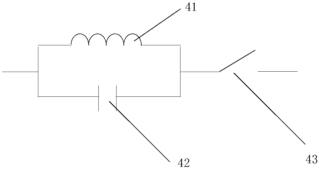
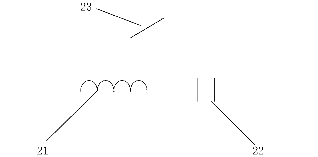
[0033] Such as figure 1 As shown, this embodiment provides a live ice melting topology system based on a resonant circuit, including an ice melting switch 7 connected in parallel to the power transmission line 3, and an ice melting switch 7 connected in series to the outside of the ice melting switch 7 for generating ice melting voltage A deicing device 8, a parallel resonant circuit 4 connected in parallel to the power transmission line 3 for short-circuiting the power transmission line 3, a first series resonant circuit 2 and a second series resonant circuit 5 connected in series on the power transmission line 3;
[0034] Wherein, the first series resonant circuit 2 is arranged between the first substation 1 and the ice melting switch 7 , and the second series resonant circuit 5 is arranged between the parallel resonant circuit 4 and the second substation 6 .
[0035] In the above system, the resonant circuit is used to melt the ice. On the one hand, it can effectively reduc...
Embodiment 2
[0050] Corresponding to the above-mentioned embodiments, this embodiment provides a resonant circuit-based electrified deicing method, including the following steps:
[0051] S1: Detect the icing situation on the transmission line 3. When the icing value on the transmission line 3 is greater than or equal to the icing warning value, short-circuit the parallel resonant circuit 4 and the transmission line 3, and disconnect the first series resonant circuit 2 and The transmission line 3, and disconnect the second series resonant circuit 5 and the transmission line 3;
[0052] S2: Adjust the gear of the ice-melting device 8, close the ice-melting switch 7 to start melting the ice until the ice on the transmission line 3 falls off, and then turn off the ice-melting switch 7.
[0053] In this embodiment, in S1, the parallel resonant circuit 4 and the power transmission line 3 are short-circuited, the first series resonant circuit 2 and the power transmission line 3 are disconnected,...
PUM
 Abstract
Description
Claims
Application Information
 - R&D Engineer
- R&D Manager
- IP Professional
- Industry Leading Data Capabilities
- Powerful AI technology
- Patent DNA Extraction
Browse by: Latest US Patents, China's latest patents, Technical Efficacy Thesaurus, Application Domain, Technology Topic, Popular Technical Reports.
© 2024 PatSnap. All rights reserved.Legal|Privacy policy|Modern Slavery Act Transparency Statement|Sitemap|About US| Contact US: help@patsnap.com