
A magnetorheological fluid shock absorb

A magnetorheological fluid and shock absorber technology, which is applied in the direction of shock absorbers, shock absorbers, springs/shock absorbers, etc., can solve problems such as inconvenient maintenance and disassembly, energy waste, and magnetorheological fluid leakage. To achieve the effect of saving energy

Inactive Publication Date: 2018-11-27
JIANGSU UNIV
View PDF7 Cites 1 Cited by
  • Summary
  • Abstract
  • Description
  • Claims
  • Application Information

AI Technical Summary

Problems solved by technology

Among them, the magnetorheological fluid shock absorber has become mature, but there are still many problems, such as coil heat dissipation, high cost of magnetorheological fluid, and energy waste.
[0004] So far, the patent application publication No. CN106763455A has proposed a pneumatic spring variable damping shock absorber assembly that can generate electricity. The control circuit is not easy to implement; the patent with the authorized publication number CN205896021U proposes a strong damping magneto-rheological fluid shock absorber with a built-in shoe-shaped iron core. The shock absorber is equipped with a magnetic field generating component inside the piston. Maintenance and disassembly Inconvenient and easy to cause magnetorheological fluid leakage; in addition, the traditional magnetorheological fluid shock absorber needs an external power supply, which does not consider the recycling of vibration energy

Method used


Image

  • A magnetorheological fluid shock absorb
  • A magnetorheological fluid shock absorb
  • A magnetorheological fluid shock absorb

Examples


Embodiment Construction

[0016] The present invention will be further described below in conjunction with the accompanying drawings and specific embodiments, but the protection scope of the present invention is not limited thereto.

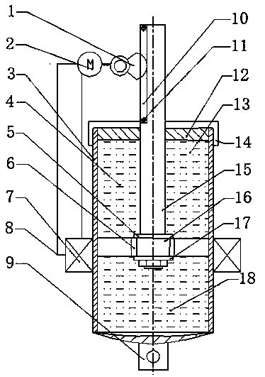
[0017] Such as figure 1 and image 3 As shown, a magnetorheological fluid shock absorber of the present invention is composed of a magnetorheological fluid shock absorber and a self-generating system; a magnetorheological fluid shock absorber includes a piston rod 15, a piston body assembly 16, and a cylinder 3 , upper cavity 4, lower cavity 18, damping hole 6, valve plate a5 and valve plate b17;

[0018] The shaft shoulder and thread are processed at the end of the piston rod 15, the nut and the piston rod 15 are threadedly connected to fix the piston body assembly 16 on the shaft shoulder of the piston rod 15, and the piston body assembly 16 is respectively provided with a valve plate a5 and a valve plate b17, There is a damping hole 6 on the piston body assembly 16; ...


PUM


Abstract

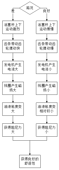
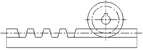
The invention discloses a magnetorheological fluid shock absorber, comprising a magnetorheological fluid shock absorber and a self-generating system. A magnetorheological fluid shock absorb comprisesa piston rod, a piston body assembly, a cylinder barrel, a damping hole and a magnetorheological fluid; Self-generating systems include generators, sector gears, and solenoids. The rack is fixed on the piston rod through bolts, and the sector gear meshes with the rack, and the sector gear is connected with the generator through a sleeve coupling, leads out wires at both ends of the generator, andconnects the electromagnetic coil to form a closed loop. The solenoid is evenly wound around the cylinder. When the automobile is running on the uneven road, the rack on the piston rod makes reciprocating linear motion to drive the sector gear to rotate, and the sector gear to drive the generator to rotate, thus producing a certain electric current. The magnitude of current affects the viscosity of MR fluid, and then changes the magnitude of damping force. The invention has the advantages of compact structure, small volume, low cost, energy saving, self-adaptive regulation of damping and the like.

Description

technical field [0001] The invention relates to the field of automobile shock absorbers, in particular to a magneto-rheological fluid shock absorber. Background technique [0002] The automobile suspension is an important structure for the automobile to transmit torque and buffer the impact force from the ground, and plays an important role in improving the comfort and safety of automobile driving. Shock absorber is an important part of automobile suspension, which has a great influence on the performance of suspension. [0003] Shock absorbers can be divided into hydraulic cylinder shock absorbers, electrorheological fluid shock absorbers and magnetorheological fluid shock absorbers from the working medium. Among them, the magnetorheological fluid shock absorber has become mature, but there are still many problems, such as coil heat dissipation, high cost of magnetorheological fluid, and energy waste. [0004] So far, the patent application publication No. CN106763455A ha...

Claims


Application Information

Patent Timeline
Patent Type & Authority Applications(China)
IPC IPC(8): F16F9/53F16F9/32F16F9/34F16F9/508F03G7/08
Inventor 谢方伟万快弟曹金鑫赵呈向柯俊钱鹏飞
Owner JIANGSU UNIV
Learn More