
Ceramic body glazing mechanism with dual-position conveying function

A technology for ceramic blanks and feeding materials, which is applied to the field of glazing of ceramic blanks, can solve the problems of low work efficiency, intermittent blanks, enamel damage, etc., and achieves the effect of improving efficiency

Inactive Publication Date: 2018-11-27
大埔县益成实业有限公司
View PDF9 Cites 0 Cited by
  • Summary
  • Abstract
  • Description
  • Claims
  • Application Information

AI Technical Summary

Problems solved by technology

[0004] Aiming at the deficiencies of the prior art, the present invention provides a double-feeding ceramic body glazing mechanism, which solves the problem that the existing glazing equipment will cause damage to the enamel on the surface of the body, and the intermittent spraying process of the body makes the work The problem of extremely low efficiency

Method used


Image

  • Ceramic body glazing mechanism with dual-position conveying function
  • Ceramic body glazing mechanism with dual-position conveying function
  • Ceramic body glazing mechanism with dual-position conveying function

Examples


Embodiment 1

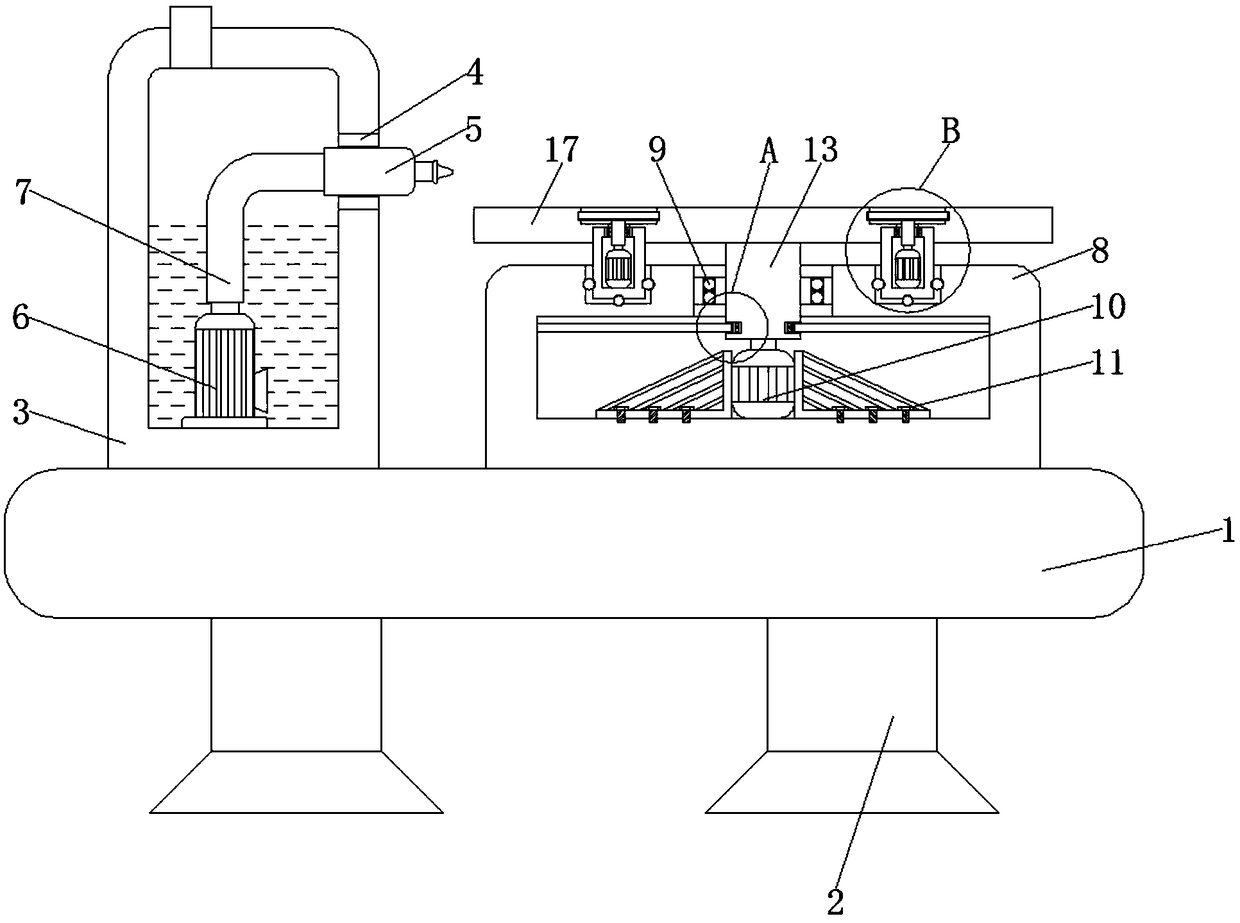
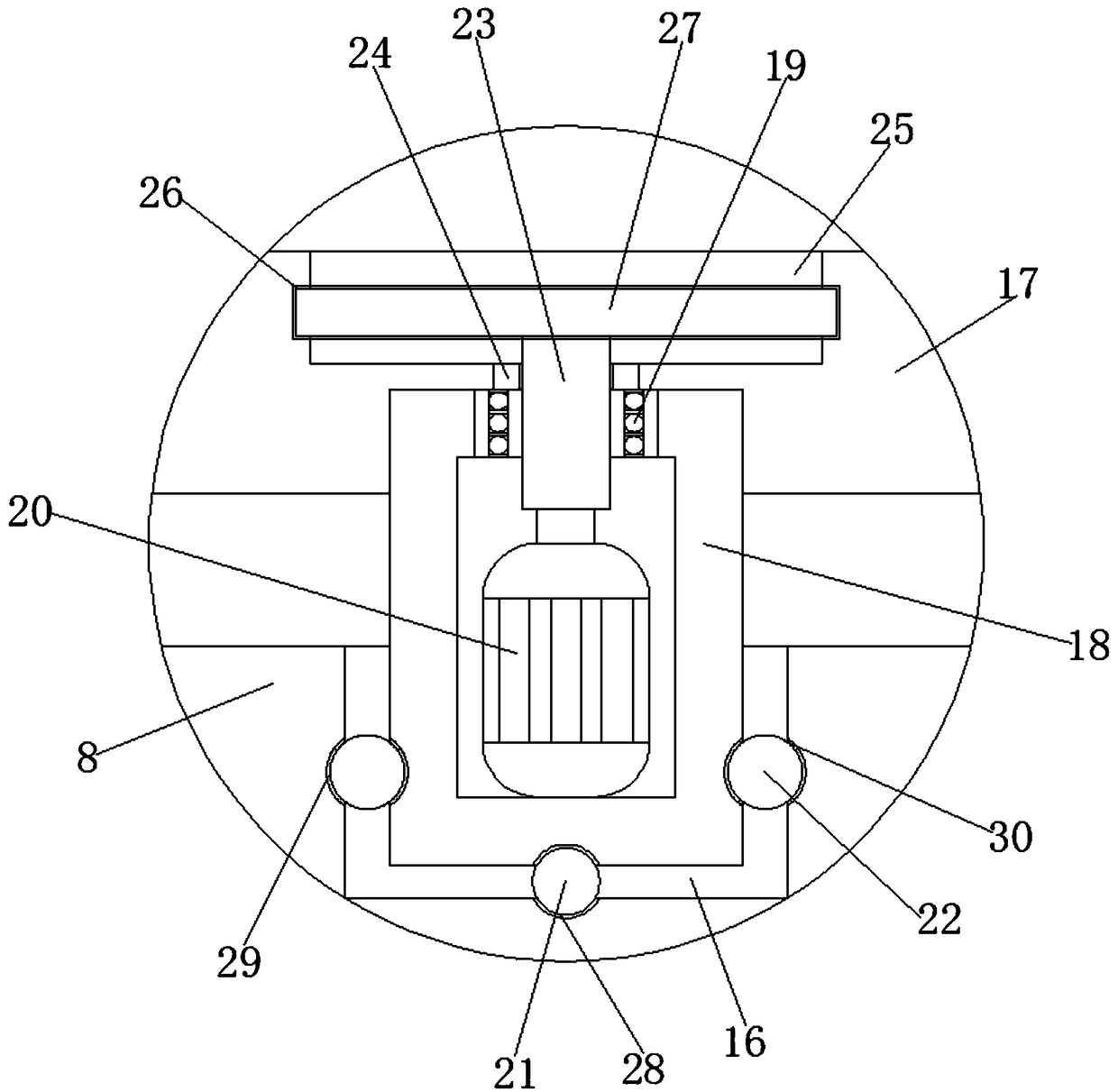
[0032] Such as Figure 1-3 As shown, a double-position feeding ceramic body glazing mechanism includes a support platform 1, support legs 2 are symmetrically fixedly connected to both sides of the bottom of the support platform 1, and a glaze storage box 3 is fixedly connected to the left side of the top of the support platform 1. The top of the right side of the glaze storage box 3 is provided with a first opening, the first opening is fixedly connected with a fixed gasket 4, the top of the right side of the glaze storage box 3 is provided with a spray gun 5, and the middle part of the bottom of the inner wall of the glaze storage box 3 is fixedly connected with a The delivery pump 6 is fixedly connected with a delivery pipe 7 in the middle of the top of the delivery pump 6 .

[0033]The right side of the top of the support table 1 is fixedly connected with a workbench 8, the middle of the top of the workbench 8 is provided with a second opening, the second opening is fixedly...

Embodiment 2

[0036] On the basis of Embodiment 1, the end of the spray gun 5 close to the glaze storage box 3 penetrates the fixed gasket 4 and extends to the inside of the glaze storage box 3, the spray gun 5 is attached to the fixed gasket 4 and fixedly connected, and the delivery pipe 7 is far away from the delivery One end of the pump 6 is fixedly connected to one end of the spray gun 5, through the cooperative work of the glaze storage box 3, the fixed gasket 4, the spray gun 5, the delivery pump 6, and the delivery pipe 7, the glaze material inside the glaze storage box 3 is absorbed. The ceramic body is sprayed with glaze to obtain a glaze layer with a suitable thickness, so that the ceramic body can be evenly glazed.

Embodiment 3

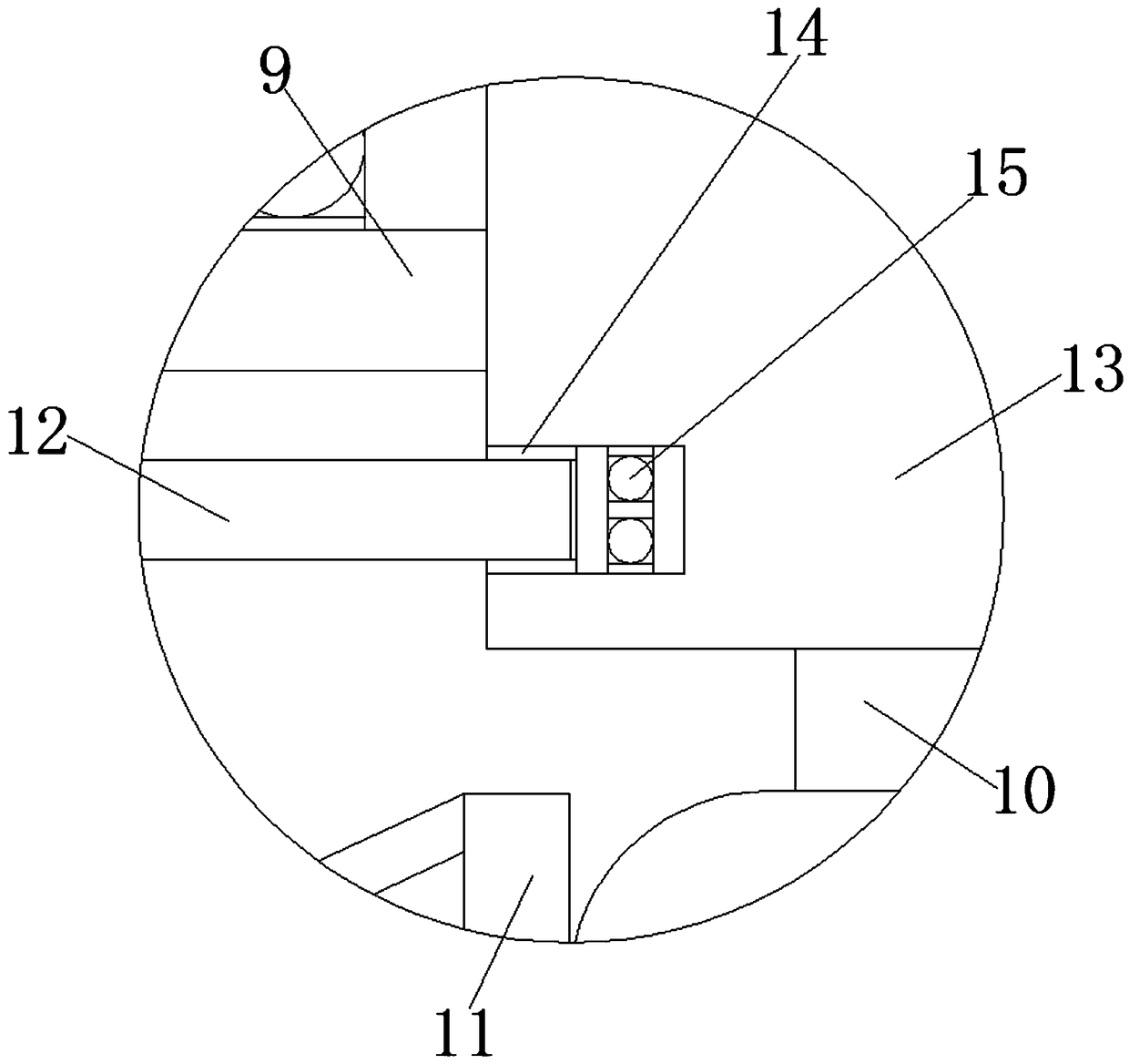
[0038] On the basis of Embodiments 1 and 2, the limit frame 11 is fixedly connected to the bottom of the inner wall of the workbench 8 by bolts, the limit frames 11 on both sides are respectively attached to the two sides of the first motor 10, and the first rotating shaft 13 The bottom runs through the first bearing 9 and extends to the inside of the workbench 8. The first rotating shaft 13 fits and is fixedly connected to the first bearing 9. An output shaft extends from the top of the first motor 10, and the output shaft of the first motor 10 is fixed. It is connected in the middle of the bottom of the first rotating shaft 13 .


PUM


Abstract

The invention discloses a ceramic body glazing mechanism with a dual-position conveying function and relates to the technical field of glazing of ceramic bodies. The ceramic body glazing mechanism comprises a support table; support legs are fixedly connected to the two sides of the bottom of the support table in symmetric manner; a glaze storage tank is fixedly connected to the left of the top ofthe support table; the top of the right side of the glaze storage tank is provided with a first opening; a fixing washer is fixedly connected to the first opening; a spray gun is arranged at the righttop of the glaze storage tank; a conveying pump is fixedly connected to the bottom center of the inner wall of the glaze storage tank; a conveying pipe is fixedly connected to the top center of the conveying pump; a worktable is fixedly connected to the right top of the support table. Ceramic bodies are arranged on the two sides of a bearing table herein, glazing is performed at one side, airingand body changing are performed at the other side; therefore, glaze is avoided being not dry and being damaged, and working efficiency is improved The problems are solved that existing glazing equipment may cause damage to surface glaze of bodies, and intermittent spraying for the bodies has low efficiency.

Description

technical field [0001] The invention relates to the technical field of glazing a ceramic body, in particular to a double-position feeding glazing mechanism for a ceramic body. Background technique [0002] At present, the glazing of products in sanitary ceramics factories is basically divided into manual glazing and automatic glazing by robots. Manual glazing is gradually replaced by automatic glazing by robots due to its labor intensity and serious environmental pollution. However, the current robot glazing is basically carried out in a semi-closed space with flowing water, which only reduces the labor intensity of the workers. Under continuous operation, the sprayed but not dry body is transported out, which will damage the enamel on the surface of the body. The other is glazing in a closed space, but when a product is sprayed, the glazing program must be closed, and the sprayed green body should be moved out before placing the unsprayed green body. The green body is spray...

Claims


Application Information

Patent Timeline
Patent Type & Authority Applications(China)
IPC IPC(8): B28B11/04
Inventor 詹骐玮詹益环黄兴诺
Owner 大埔县益成实业有限公司
Learn More