


Quick Research
Generate reliable direction feasibility study reports for your R&D in just a few steps.

Technical Q&A
Discover and master advanced knowledge NOW. Basics, ideas, possibilities, all at once.

Find Solutions
As an expert in R&D theories, this can generate solutions to your technical problems instantly.

Evaluate Feasibility
Analyze your overall solution with one click, know your potential R&D risks in advance.

Monitor Landscape
Get weekly tech updates, stay abreast of the latest tech innovations and key insights.
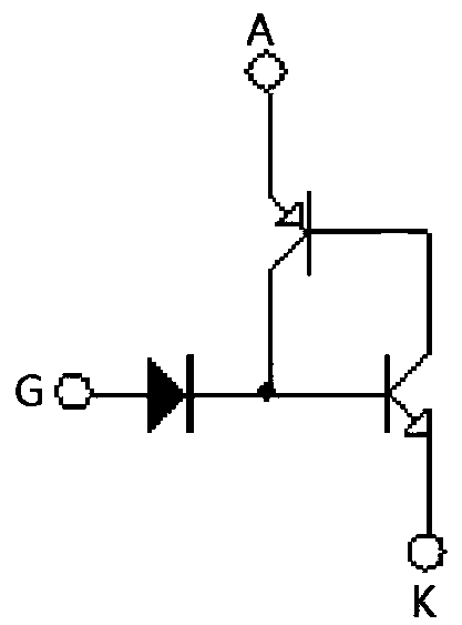
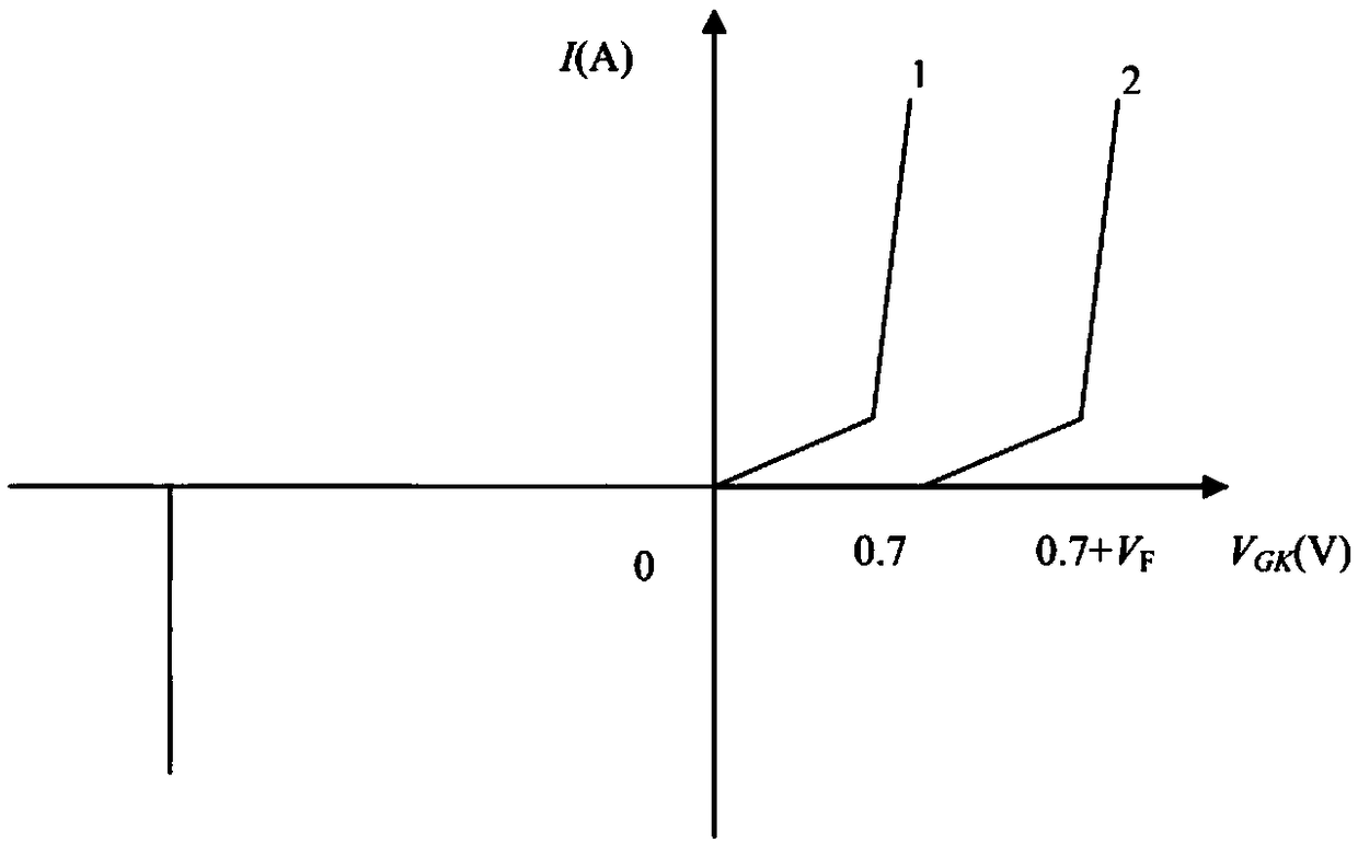
High trigger voltage thyristor
A trigger voltage and thyristor technology, applied in the direction of thyristors, diodes, etc., can solve the problems of thyristor false opening, high trigger voltage, low trigger voltage, etc., achieve small packaging stress, improve reliability, and high liquidus Effect
- Summary
- Abstract
- Description
- Claims
- Application Information
AI Technical Summary
Problems solved by technology
Method used
Image

Examples
Embodiment 1
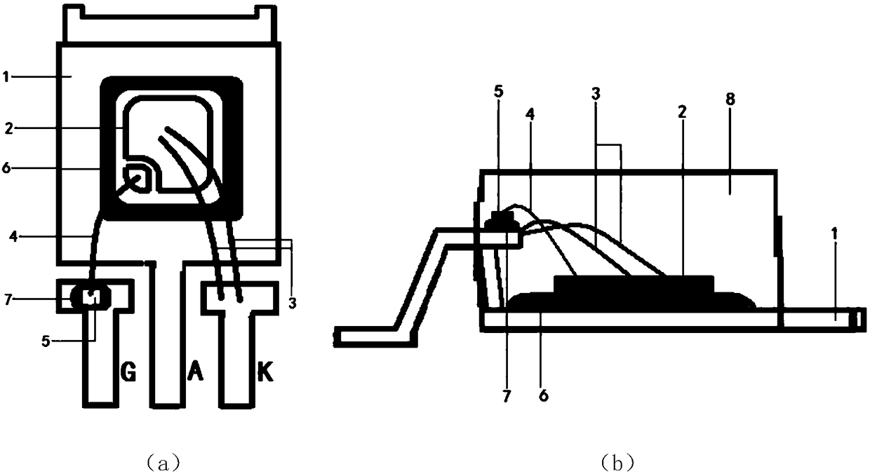
[0033] S1: First select a metal frame, which is a KFC (CuFe_0.1P_0.03) copper frame with a thickness of 0.5 mm.
[0034] S2: Point solder on the PAD of the anode A on the copper frame, the solder is Pb / Sn / Ag=92.5:5:2.5, and point conductive silver paste on the PAD of the control pole G of the copper frame.
[0035] S3: Glue a thyristor chip on the solder on the PAD of the anode A on the copper frame, and glue a diode chip on the conductive silver paste on the PAD of the control electrode G of the copper frame. By sintering, the thyristor chip is well adhered to the anode A on the copper frame, and the diode chip is well adhered to the gate G of the copper frame.
[0036] S4: Pressure-weld two high-purity aluminum wires between the larger cathode bonding area of the thyristor chip and the K-electrode pin of the copper frame. The high-purity aluminum wires have a purity of 99.99% and a diameter of 12 mils.
[0037] S5: Press-weld a high-purity gold wire between the small cont...
Embodiment 2
[0040] S1: First select a metal frame, which is a KFC (CuFe_0.1P_0.03) copper frame with a thickness of 0.5 mm.
[0041] S2: Point solder on the PAD of the anode A on the copper frame, the solder is Pb / Sn / Ag=92.5:5:2.5, and point conductive silver paste on the PAD of the control pole G of the copper frame.
[0042]S3: Glue a thyristor chip on the solder on the PAD of the anode A on the copper frame, and glue a diode chip on the conductive silver paste on the PAD of the control electrode G of the copper frame. By sintering, the thyristor chip is well adhered to the anode A on the copper frame, and the diode chip is well adhered to the gate G of the copper frame.
[0043] S4: Pressure-weld two high-purity aluminum wires between the relatively large cathode bonding area of the thyristor chip and the K-electrode pin of the copper frame. The high-purity aluminum wires have a purity of 99.99% and a diameter of 10 mils.
[0044] S5: Press-weld a high-purity gold wire between the s...
Embodiment 3
[0047] S1: First select a metal frame, which is a KFC (CuFe_0.1P_0.03) copper frame with a thickness of 0.5 mm.
[0048] S2: Point solder on the PAD of the anode A on the copper frame, the solder is Pb / Sn / Ag=92.5:5:2.5, and point conductive silver paste on the PAD of the control pole G of the copper frame.
[0049] S3: Glue a thyristor chip on the solder on the PAD of the anode A on the copper frame, and glue a diode chip on the conductive silver paste on the PAD of the control electrode G of the copper frame. By sintering, the thyristor chip is well adhered to the anode A on the copper frame, and the diode chip is well adhered to the gate G of the copper frame.
[0050] S4: Pressure-weld two high-purity aluminum wires between the relatively large cathode bonding area of the thyristor chip and the K-electrode pin of the copper frame. The high-purity aluminum wires have a purity of 99.99% and a diameter of 15 mils.
[0051] S5: Press-weld a high-purity gold wire between the ...
PUM
 Abstract
Description
Claims
Application Information
 - R&D Engineer
- R&D Manager
- IP Professional
- Industry Leading Data Capabilities
- Powerful AI technology
- Patent DNA Extraction
Browse by: Latest US Patents, China's latest patents, Technical Efficacy Thesaurus, Application Domain, Technology Topic, Popular Technical Reports.
© 2024 PatSnap. All rights reserved.Legal|Privacy policy|Modern Slavery Act Transparency Statement|Sitemap|About US| Contact US: help@patsnap.com