Low-loss coupler
A coupler and low-loss technology, applied in the field of couplers, can solve the problem that the plug is difficult to resist external force impact, and achieve the effects of reducing the risk of impact bending or even damage, improving the bearing capacity and improving the protection ability
- Summary
- Abstract
- Description
- Claims
- Application Information
AI Technical Summary
Problems solved by technology
Method used
Image
Examples
Embodiment 1
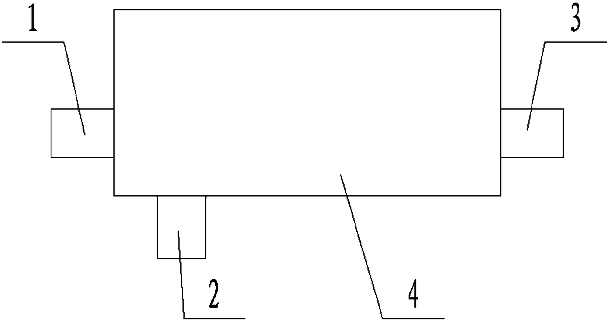
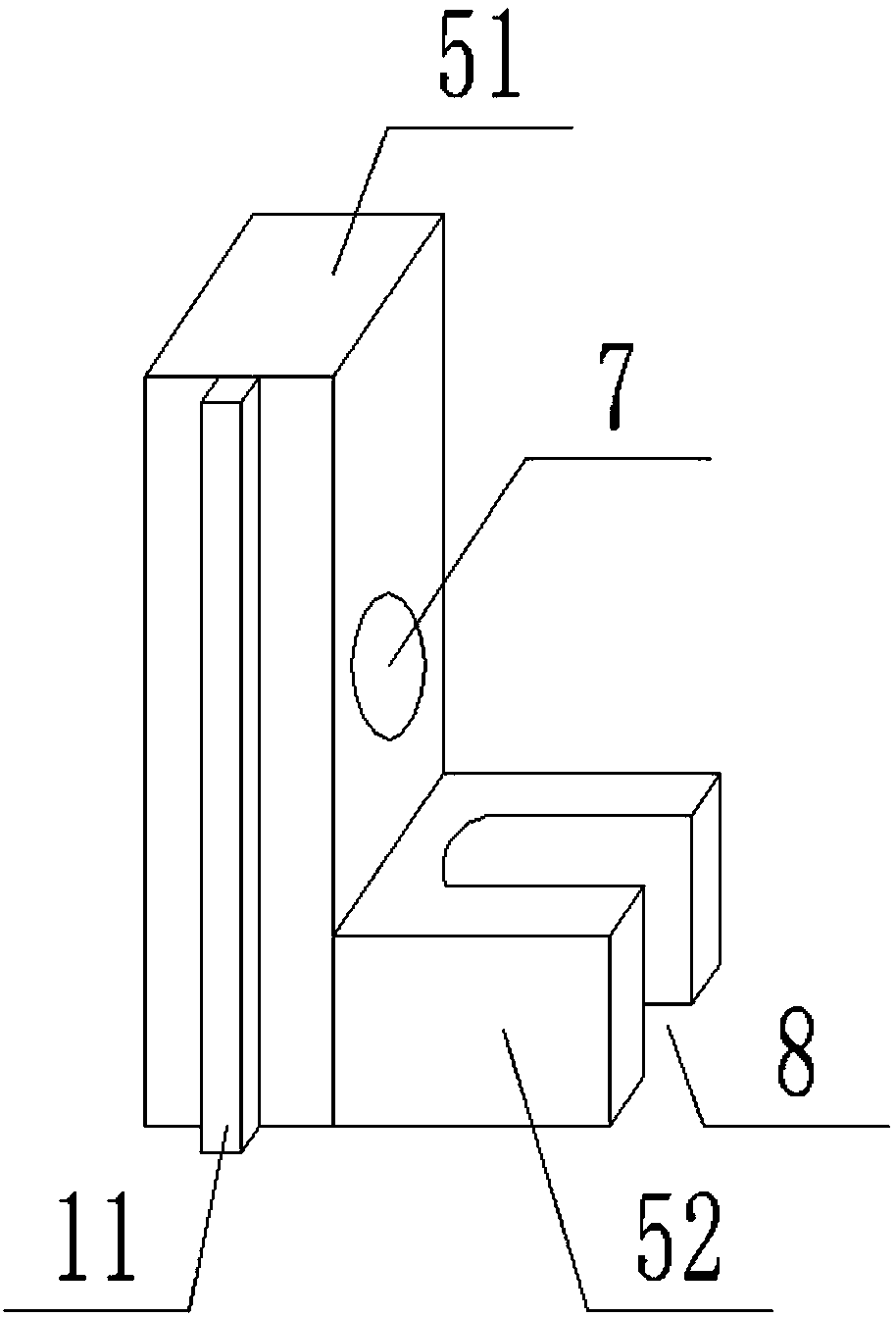
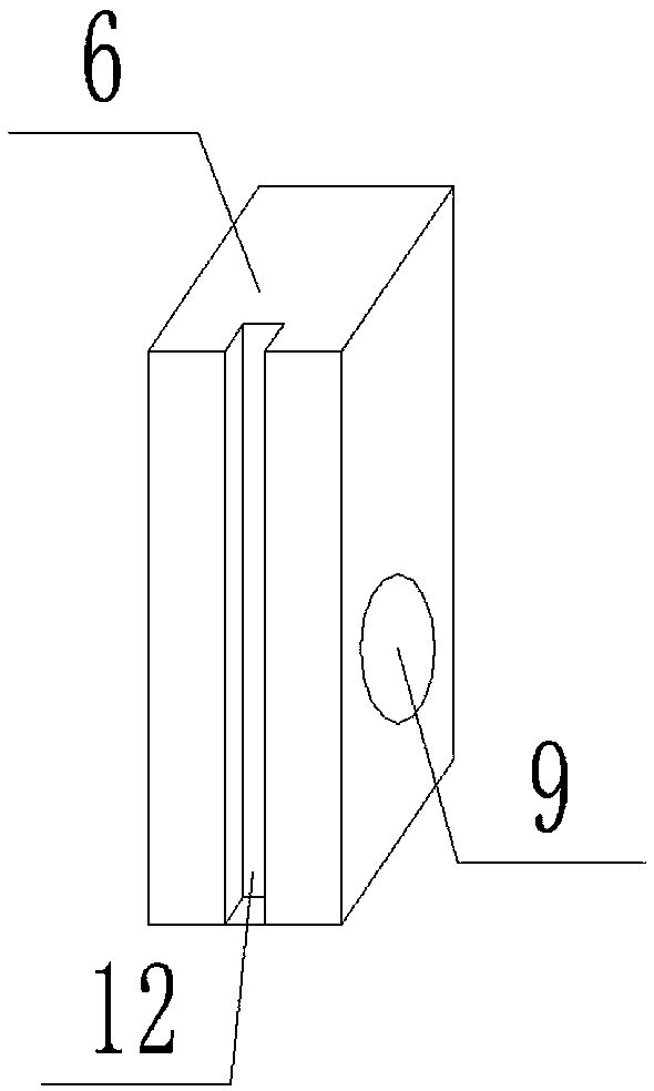
[0024] Such as Figure 1 to Figure 5A low-loss coupler shown includes a coupler body 4 with three plugs, the coupler body 4 is square, and the three plugs are respectively a first plug 1, a second plug 2, and a third plug. The plug 3, the first plug 1, the second plug 2, and the third plug 3 are respectively located on one side surface of the coupler body 4, and the first plug 1 and the third plug 3 are respectively located on opposite sides of the coupler body 1, The distance between the second plug 2 and the first plug 1 is smaller than the distance between the second plug 2 and the third plug 3; it also includes a first end cover 5 and a second end cover 6, and the first end The cover 5 is made up of a first connecting block 51 and a second connecting block 52 which are at right angles to each other. The first connecting block 51 is provided with a first through hole 7, and the inner diameter of the first through hole 7 is larger than the inner diameter of the first through...
Embodiment 2
[0026] Such as Figure 1 to Figure 5 In the shown low-loss coupler, on the basis of Embodiment 1, the thickness of the first connection block 51 is greater than the length of the first plug 1; the thickness of the second connection block 52 is greater than the length of the second plug 2 length. The linear protrusion 11 is located on the first connecting block 51 , and the long axis of the linear protrusion 11 is perpendicular to the axis of the first through hole 7 . A rubber band 10 is also included, and both the first end cover 5 and the second end cover 6 are connected to the coupler body 4 through the rubber band 10 . A layer of sponge is laid on the inner walls of the first through hole 7 , the second through hole 9 and the U-shaped groove 8 .
PUM
 Abstract
Description
Claims
Application Information
 - R&D Engineer
- R&D Manager
- IP Professional
- Industry Leading Data Capabilities
- Powerful AI technology
- Patent DNA Extraction
Browse by: Latest US Patents, China's latest patents, Technical Efficacy Thesaurus, Application Domain, Technology Topic, Popular Technical Reports.
© 2024 PatSnap. All rights reserved.Legal|Privacy policy|Modern Slavery Act Transparency Statement|Sitemap|About US| Contact US: help@patsnap.com


