
Oil distribution valve

A technology of oil distribution valve and valve hole, which is applied in the field of hydraulic valves, can solve the problems of large leakage, time-consuming, and high maintenance costs, and achieve the effects of reducing maintenance costs, reducing convenience, and compact volume

Inactive Publication Date: 2018-11-23
宁波真格液压科技有限公司
View PDF4 Cites 2 Cited by
  • Summary
  • Abstract
  • Description
  • Claims
  • Application Information

AI Technical Summary

Problems solved by technology

The oil distribution valves in the prior art have two structures: spool valve type and cone valve type. The structure of the spool valve type oil distribution valve is simple and easy to process. Low, the leakage is large when the pressure rises, so that the micro hydraulic power unit cannot reach a higher pressure; the cone valve type oil distribution valve is a cone seal structure, and the sealing performance is good, which can make the micro hydraulic power unit reach a higher pressure. pressure level, but the poppet valve oil distribution valve in the prior art has a two-stage structure, including the first poppet spool and the second poppet spool. The connecting rod of the first poppet spool protrudes out of the valve hole, and then the second poppet spool is installed on the valve stem on the first poppet spool with interference, so that the first poppet spool and the second poppet spool form a As a whole, the installation process is very complicated and time-consuming, and when the poppet spool oil distribution valve is damaged, it cannot be disassembled, and the entire valve block needs to be replaced, resulting in high maintenance costs

Method used


Image

  • Oil distribution valve
  • Oil distribution valve
  • Oil distribution valve

Examples


Embodiment Construction

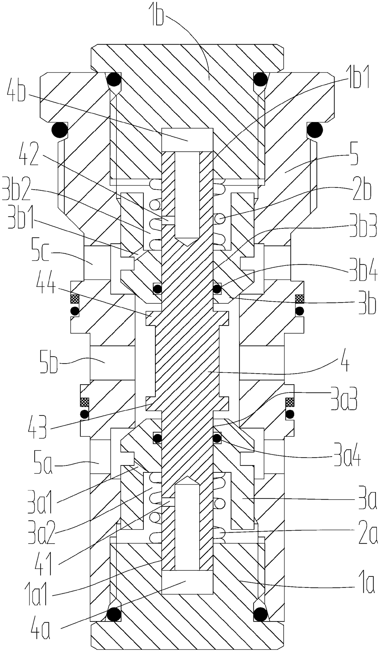
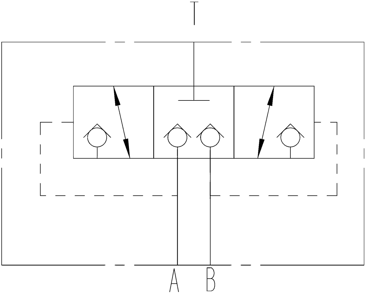
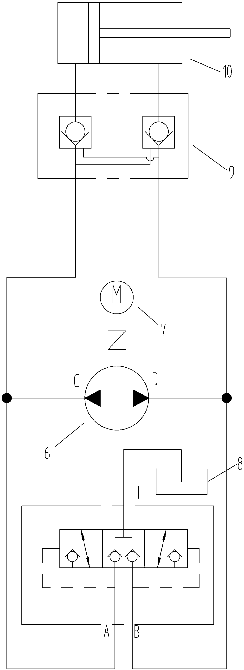
[0019] see Figure 1-5 As shown, the present invention provides an oil distribution valve, which includes a valve sleeve 5 and a control rod 4. A first threaded hole 501 and a first valve hole 502 communicating with each other are arranged coaxially in the valve sleeve 5 in sequence from bottom to top. , a communication hole 503 , a second valve hole 504 , and a second threaded hole 505 . A port 5a communicating with the first valve hole 502 , a port T 5b communicating with the communicating hole 503 , and a port communicating with the second valve hole 504 are provided on the circumferential side of the valve sleeve 5 . B port 5c. The first valve hole 502 is slidably connected with the first taper spool 3a for controlling the on-off of the T oil port 5b and the A oil port 5a, and the second valve hole 504 is slidably connected with the T oil port 5b and the A oil port 5a. The B oil port 5c connects and disconnects the second poppet spool 3b. The valve sleeve 5 is provided ...


PUM


Abstract

The invention discloses an oil distribution valve. The oil distribution valve comprises a valve sleeve and a control rod, wherein the valve sleeve is internally and coaxially provided with a first thread hole, a first valve hole, a communication hole, a second valve hole and a second thread hole in sequence from bottom to top; an A oil opening, a T oil opening and a B oil opening are formed in theperipheral side face of the valve sleeve; the first valve hole is internally connected with a first cone valve element in a sliding manner; the second valve hole is internally connected with a secondcone valve element in the sliding manner; a first screw plug is connected into the first thread hole through a thread; a first spring is arranged in the valve sleeve and is located between the firstscrew plug and the first cone valve element; a second screw plug is connected into the second thread hole through a thread; a second spring is arranged in the valve sleeve and is located between the second screw plug and the second cone valve element; the control comprises a rod body located in the communication hole, an upper rod which is arranged at the upper end of the rod body and extends in the direction of the second thread hole and a lower rod which is arranged at the lower end of the rod body and extends in the direction of the first thread hole. The oil distribution valve can be reliably sealed, is simple in structure and convenient to process and repair.

Description

technical field [0001] The invention relates to the technical field of hydraulic valves, in particular to an oil distribution valve. Background technique [0002] The oil distribution valve is an important hydraulic component used in the micro hydraulic power unit. Its main function is to cooperate with the two-way hydraulic pump. When the motor is switched forward and reverse, it automatically switches the connection between the two oil ports of the two-way hydraulic pump and the fuel tank. The oil distribution valves in the prior art have two structures: spool valve type and cone valve type. The structure of the spool valve type oil distribution valve is simple and easy to process. Low, the leakage is large when the pressure rises, so that the micro hydraulic power unit cannot reach a higher pressure; the cone valve type oil distribution valve is a cone seal structure, and the sealing performance is good, which can make the micro hydraulic power unit reach a higher pressur...

Claims


Application Information

Patent Timeline
Patent Type & Authority Applications(China)
IPC IPC(8): F15B13/042F15B21/08F16K11/04
CPCF15B13/042F15B21/08F16K11/04
Inventor 不公告发明人
Owner 宁波真格液压科技有限公司
Learn More