Piling-machine chain drill bit high in controllability

A chain and machine-chain technology, which is applied to drilling tools, sheet pile walls, drilling equipment, etc., can solve problems such as block phenomenon, high driving power, and easy failure, so as to reduce the effective area and improve the excavation efficiency , Improve the effect of structural strength

Inactive Publication Date: 2018-11-23
周兆弟
View PDF1 Cites 0 Cited by
  • Summary
  • Abstract
  • Description
  • Claims
  • Application Information

AI Technical Summary

Problems solved by technology

This kind of pile drill bit uses a spiral blade to cut and pulverize the soil. The size of the blade or the cutter head is relatively large, and the cut rock and soil are relatively large in size, and even blocky, which will lead to the following problems: 1. During the production process of the mixing pile, the cement slurry cannot enter the "blocked rock and soil", resulting in the presence of massive rock and soil in the concrete mixing pile, resulting in a significant decrease in the compressive and bearing capacity of the concrete mixing pile; ② When drilling the silt layer And when making concrete mixing piles, there may be a soil squeezing effect, which makes the bottom of the concrete mixing piles hollow, and the phenomenon of "floating piles" appears, resulting in unstable foundations of cement-soil mixing piles
This kind of chain-knife-type mixing pile wall-forming equipment is mostly used in excavating groove-type foundations. The chain-knife cutting box assembly has a large volume, large driving power, and high energy consumption, and its power is set on the top of the pile frame, which means The drive chain is longer, which not only makes the power efficiency low, but also prone to failure
In addition, there is still a technical problem of poor soil crushing effect due to the relatively large width horizontal cutters arranged on the chain rail

Method used


Image

  • Piling-machine chain drill bit high in controllability
  • Piling-machine chain drill bit high in controllability
  • Piling-machine chain drill bit high in controllability

Examples


Embodiment 1

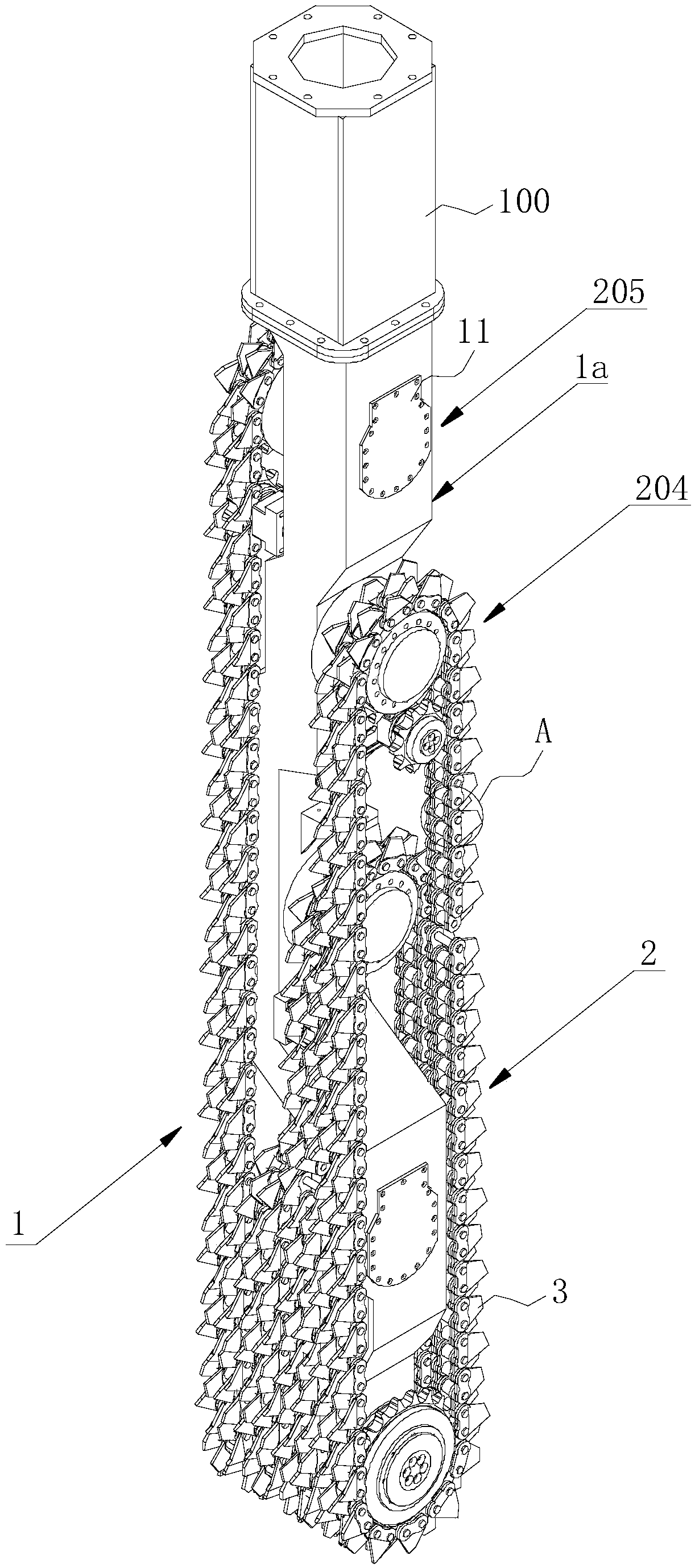
[0117] Such as Figure 17 As shown, a chain drill bit with sufficient soil stirring includes a cutting carrier 101 located at the lower part of the drill rod that can rotate along the circumferential direction and is connected end to end (obviously, the cutting carrier 101 is a more specific form of the chain carrier , when the chain carrier is ring-shaped and the working mode is circumferential rotation, the chain carrier is the above-mentioned cutting carrier 101; this will not be described in detail below), the surface of the cutting carrier 101 has a raised structure 2, The cutting carrier 101 includes an endless chain 1 connected with a power mechanism. The power mechanism connected to the endless chain 1 is located at the lower part of the drill pipe to form a power down position. The surface of the endless chain 1 has a raised structure 2 . Preferably, when the endless chain 1 is connected with the drill pipe 100, the endless chain 1 is arranged vertically, that is, whe...

Embodiment 2

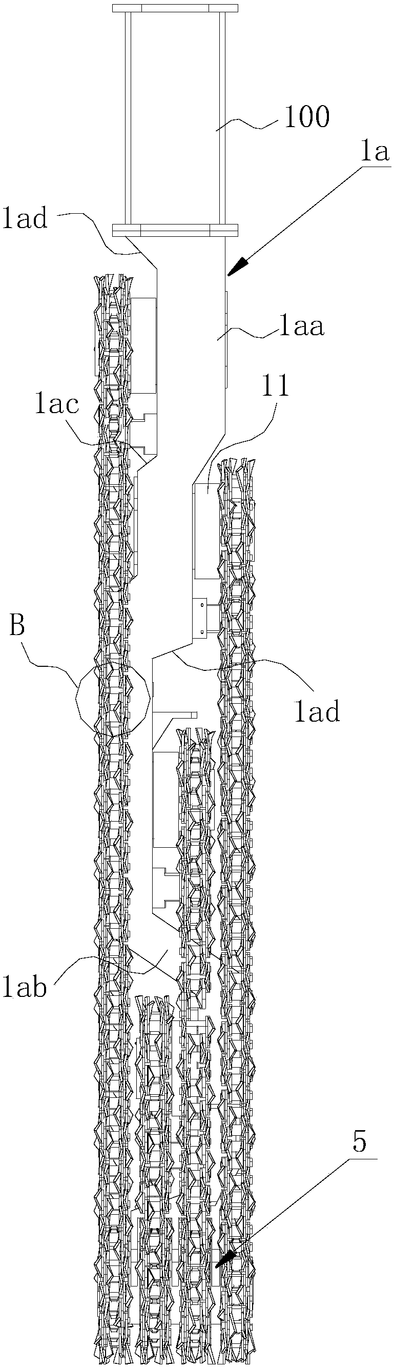
[0144] The structure and working principle of this embodiment are basically the same as that of Embodiment 1, the difference is that in combination Figure 20 and Figure 21 As shown, there are two endless chains 1 and they are parallel to each other, and the two endless chains 1 are not on the same plane, that is, there is a gap between the two endless chains 1, and the two endless chains 1 ends are provided with a Auxiliary cutting assembly 4 that rotates. Apparently, under the guidance of this solution, those skilled in the art can design a solution for combining three, four or more endless chains 1 . The auxiliary cutting assembly 4 of this embodiment is basically the same as that of the first embodiment, and the auxiliary chain 9 is arranged laterally, matching the width of the endless chain 1 .

[0145] In the present embodiment, the endless chain 1 is rectangular, and each corner is provided with a sprocket, one or two of which are driving sprockets 1b, and the other ...

Embodiment 3

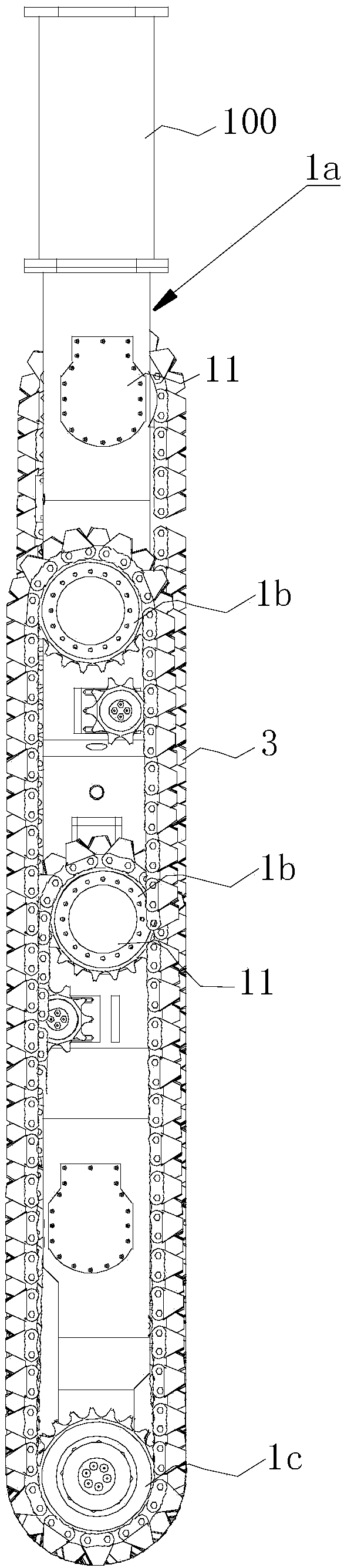
[0149] The structure and working process of this embodiment and embodiment 2 are basically the same, the difference is that, as Figure 22 and Figure 23 As shown, the driving mechanism 11 in this embodiment is arranged in the gap between the two endless chains 1, and the output end of the driving mechanism 11 is directly connected to the driving sprocket 1b on the endless connecting body. The drill rod 100 is directly connected to the driving mechanism 11 .


PUM

PropertyMeasurementUnit
Pile lengthaaaaaaaaaa

Abstract

The invention discloses a piling-machine chain drill bit high in controllability. The piling-machine chain drill bit includes a chain rack, at least one chain carrier is arranged on the chain rack, and a plurality of cutting teeth are arranged on the chain carriers; the outer ends of the cutting teeth protrude from the chain carriers and face the outer sides of the chain carriers, and chain drivemechanisms are arranged between the chain carriers and the chain rack so as to drive the chain carriers to do circumferential rotation or reciprocating swing on the chain rack; the chain rack is located on the lower portion of a drill rod and provided with a power device, and the power device includes a plurality of drive mechanisms corresponding to the chain drive mechanisms one to one. The structure facilitates the independent work of each chain carrier and the independent control of the running speed and direction of each chain carrier, and the whole soil excavation and stirring process ismore controllable.

Description

[0001] The present invention claims the priority of the Chinese utility model patent application whose application date is "May 12, 2017" and the application number is "2017205251560" and the name is "soil fully agitating type chain drill bit", and requires the application date to be "2017 On December 12, 2017, the priority of the Chinese invention patent application with the application number "2017113202359" and the name "chain drill for pile driver and pile driver", the entire content of which is incorporated in this application. technical field [0002] The invention belongs to the technical field of pile driver equipment, and relates to cement mixing pile forming equipment, in particular to a pile driver and its chain drill bit and related parts or assemblies, in particular to a pile driver chain drill bit with strong controllability. Background technique [0003] Cement mixing pile foundation is an effective form of soft foundation treatment. It usually uses cement as t...

Claims


Application Information

Patent Timeline
IPC IPC(8): E21B11/06E21B4/16E02D5/46
CPCE21B4/16E21B11/06E21B12/00E21B12/06E02D5/187E02D5/46
Inventor 周兆弟
Owner 周兆弟
Why Eureka
Try Eureka