Separated bracket node structure for steel structure beam column connection, manufacturing method and residential structure system
A technology of beam-column connection and corbel joint, which is applied in the direction of building structure and construction, can solve the problems of long welding time, difficult control of construction quality, heavy welding workload, etc., achieve good seismic performance and reduce component connection parts , The effect of speeding up the construction speed
- Summary
- Abstract
- Description
- Claims
- Application Information
AI Technical Summary
Problems solved by technology
Method used
Image
Examples
Embodiment 1
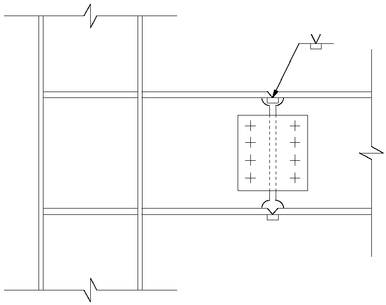
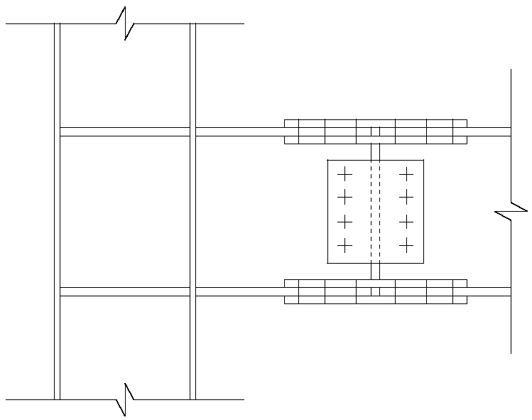
[0050] to combine Figure 2 to Figure 4 As shown, this embodiment provides a separate corbel node structure for beam-to-column connection of steel structures, including: a steel column 1 and a steel beam 2; wherein,
[0051] The end of the steel column 1 is provided with a flange base 4, and the outer wall of the steel column 1 is provided with a separate corbel flange plate 3 at a predetermined length from the flange base 4;
[0052] The flange bases 4 at the ends of the adjacent upper and lower steel columns 1 are connected by high-strength bolts, and the ends of the steel beams 2 are clamped between the flange bases 4 at the ends of the adjacent upper and lower steel columns. In between, the upper and lower flanges of the steel beam 2 are fixedly connected to the flange bases 4 at the ends of the upper and lower steel columns respectively through high-strength bolts 7 .
[0053] In this embodiment, as a further technical solution, the distance between the flange bases 4 at...
Embodiment 2
[0058] to combine Figure 5 to Figure 7 As shown, this embodiment provides a method for manufacturing a separate corbel node structure for beam-to-column connection of steel structures, including the following steps:
[0059] S1: Connect the lower flange of the steel beam 2 to the flange base of the lower steel column through high-strength bolts;
[0060] S2: Connect the flange bases of the upper and lower steel columns through high-strength bolts 7;
[0061] S3: Connect the upper flange of the steel beam to the flange base of the upper steel column through high-strength bolts 7 .
[0062] To sum up, the joint structure of the present invention eliminates the on-site butt penetration welding at the flange of the bolt-welded joint and the joint of the column, and realizes the full-bolt assembly on the construction site. At the same time, compared with the traditional full-bolt joint, the Bolts in the beam web section. The shelving and lapping method of the flange is convenie...
Embodiment 3
[0064] like Figure 8-10 As shown, the present invention also discloses a residential structure system with the above node structure, which includes: vertical load-bearing columns, horizontal load-bearing units 20 and prefabricated floor slabs 30;
[0065] Vertical load-bearing column The vertical load-bearing column includes several steel columns connected up and down in sequence;
[0066] The lateral load-bearing unit 20 includes: a lateral load-bearing frame and an enclosure wall 21 arranged outside the lateral load-bearing frame; the lateral load-bearing frame includes a steel beam 2 placed horizontally on the upper edge of the enclosure wall 21; a plurality of vertical load-bearing columns as The vertical load-bearing structure of the building is erected in parallel at intervals; the horizontal load-bearing unit 20 is arranged between two adjacent vertical load-bearing columns; The end 2a is connected to the steel column through the separated corbel node structure;
[0...
PUM
 Abstract
Description
Claims
Application Information
 - R&D Engineer
- R&D Manager
- IP Professional
- Industry Leading Data Capabilities
- Powerful AI technology
- Patent DNA Extraction
Browse by: Latest US Patents, China's latest patents, Technical Efficacy Thesaurus, Application Domain, Technology Topic, Popular Technical Reports.
© 2024 PatSnap. All rights reserved.Legal|Privacy policy|Modern Slavery Act Transparency Statement|Sitemap|About US| Contact US: help@patsnap.com


