
Driving mechanism

A technology for driving mechanisms and driving motors, which is applied to motor vehicles, aerospace vehicle power supply systems, aerospace equipment, etc., and can solve problems such as the inability to reciprocally control the deployment and retraction of spacecraft mechanisms and equipment

Active Publication Date: 2018-11-23
BEIJING SPACE TECH RES & TEST CENT
View PDF6 Cites 1 Cited by
  • Summary
  • Abstract
  • Description
  • Claims
  • Application Information

AI Technical Summary

Problems solved by technology

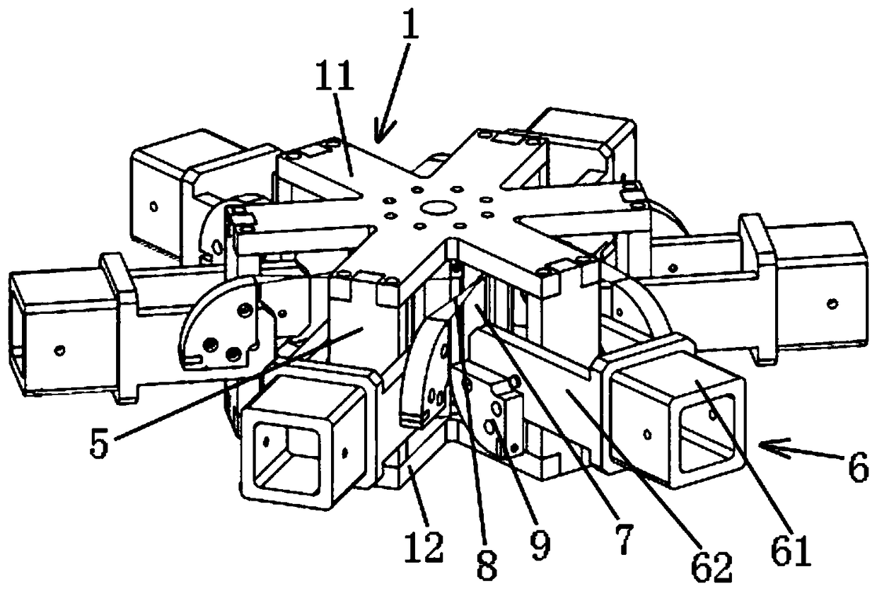
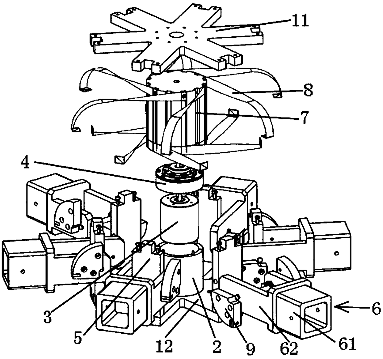
[0004] The purpose of the present invention is to provide a driving mechanism with a simple structure to solve the problem that the driving mechanism in the prior art cannot reciprocally control the deployment and retraction of the spacecraft mechanism and equipment

Method used


Image

  • Driving mechanism
  • Driving mechanism
  • Driving mechanism

Examples


Embodiment Construction

[0048] In order to more clearly describe the embodiments of the present invention or the technical solutions in the prior art, the following will briefly introduce the drawings that are used in the embodiments. Apparently, the drawings in the following description are only some embodiments of the present invention, and those skilled in the art can also obtain other drawings according to these drawings without creative efforts.

[0049] When describing the embodiments of the present invention, the terms "vertical", "transverse", "upper", "lower", "front", "rear", "left", "right", "vertical", " The orientation or positional relationship expressed by "horizontal", "top", "bottom", "inner" and "outer" is based on the orientation or positional relationship shown in the relevant drawings, which are only for the convenience of describing the present invention and simplifying the description, and It is not to indicate or imply that the device or element referred to must have a particu...


PUM


Abstract

The invention relates to a driving mechanism. The driving mechanism comprises a rack (1), a sleeve (2), a speed reducer (4), at least two connecting plates (5), a drum wheel (7) and traction belts (8). The rack (1) includes a first cover plate (11) and a second cover plate (12); the sleeve (2) is fixed to the second cover plate (12) and internally provided with a driving motor (3); the speed reducer (4) is supported on the sleeve (2) and connected to the driving motor (3); one end of each connecting plate (5) is connected with the first cover plate (11), the other end of each connecting plate(5) is connected with the second cover plate (12), and rocker arms (6) are installed on the connecting plates (5); the sleeve (2) is sleeved with the drum wheel (7) which is connected to the speed reducer (4); one end of each traction belt (8) is connected with the drum wheel (7), and the other end of each traction belt (8) is connected with the corresponding rocker arm (6). The driving mechanismhas a simple structure and can control mechanisms and equipment which are correlated to a spacecraft to be repeatedly unfolded and retracted several times.

Description

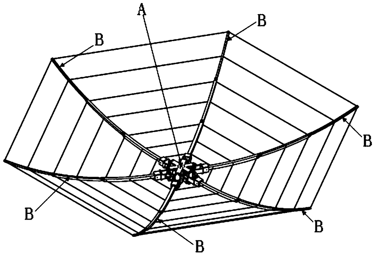
technical field [0001] The invention relates to a driving mechanism for spacecraft equipment, in particular to a driving mechanism that can drive a spacecraft parabolic communication antenna, a sun umbrella battery or a space grabbing device to expand and retract. Background technique [0002] Modern spacecraft are generally equipped with various mechanisms and equipment, which are used to realize various actions in orbit to meet the mission requirements of the spacecraft. Then these institutional devices often need to change different attitudes during different flight stages of the spacecraft. For example, deep-space exploration spacecraft such as the Galileo Jupiter probe are equipped with large-scale deployable high-gain parabolic antennas, which are used to realize deep-space long-distance communication with the ground during the detection of Jupiter. This parabolic antenna should be in a retracted state when the spacecraft is launched, so as to withstand the vibration ...

Claims


Application Information

Patent Timeline
IPC IPC(8): B64G1/22B64G1/44B64G1/66
CPCB64G1/22B64G1/222B64G1/44B64G1/66
Inventor 邵立民杨淑利
Owner BEIJING SPACE TECH RES & TEST CENT
Learn More