
Forming machining knife

A forming processing and cutting tool technology, which is applied in the direction of manufacturing tools, metal processing equipment, and cutting tools for lathes, etc., can solve the problems of inability to achieve high-efficiency and high-precision processing, achieve good cutting stability, and reduce process difficulty , Improve the effect of production quality

Pending Publication Date: 2018-11-23
OKE PRECISION CUTTING TOOLS CO LTD
View PDF0 Cites 1 Cited by
  • Summary
  • Abstract
  • Description
  • Claims
  • Application Information

AI Technical Summary

Problems solved by technology

[0005] The technical problem to be solved by the present invention is to aim at the "self" type structure of the forming blade in the prior art, that is, the upper part protrudes in a certain arc, and the lower part is a transverse inscribed groove, which cannot achieve high-efficiency and high-precision processing To provide a high-efficiency, high-precision molding tool that not only meets the requirements for slotting of normal parts, but also meets the requirements for special processing structures for slotting.

Method used


Image

  • Forming machining knife
  • Forming machining knife
  • Forming machining knife

Examples


Embodiment 1

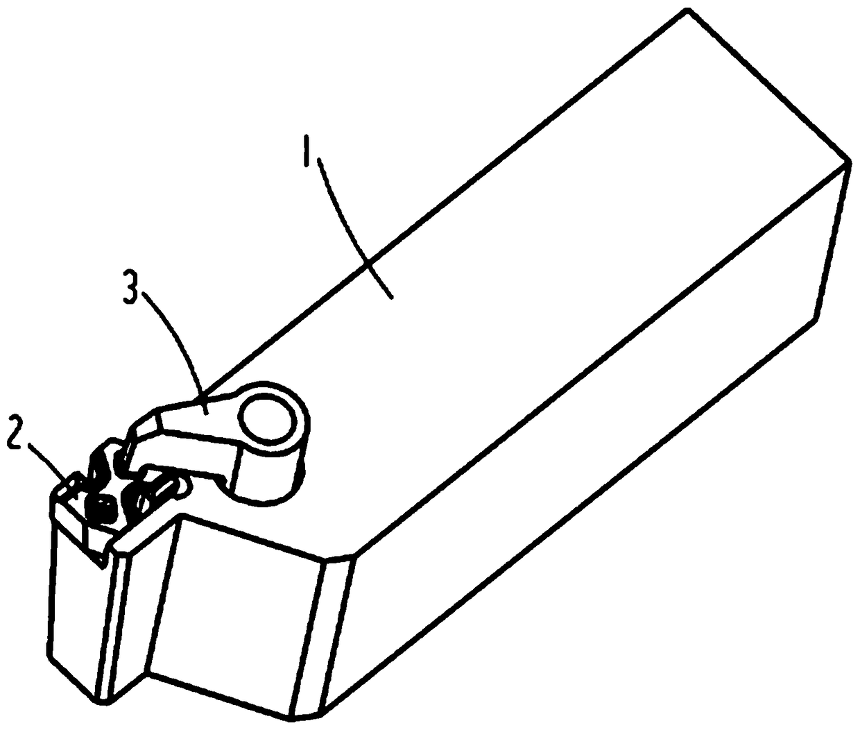
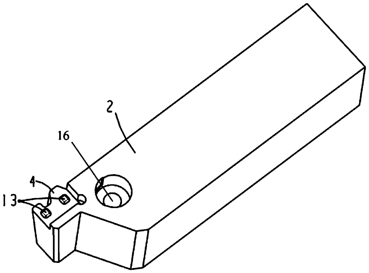
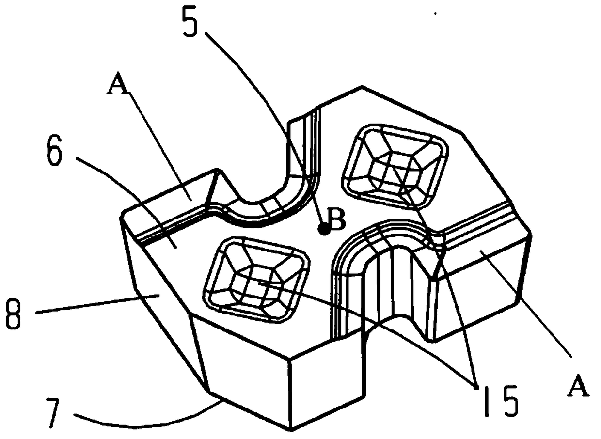
[0034] Provide a forming tool, such as figure 1 As shown, a tool for forming processing includes a tool bar 1 and an indexable cemented carbide blade 2. The indexable cemented carbide blade 2 includes a blade body 5, and the blade body 5 is a polygonal body including an upper end surface 6, the lower end surface 7, and a plurality of planar side surfaces and a plurality of arc-shaped side surfaces 8; the upper end surface 6 of the blade body 5 is provided with two cutting units A centered on the center point B of the blade, and the upper end surface is provided with the above The center point of the circular arc edge 97 of the lower cutting unit A connects with the two grooves 15 whose axis of symmetry is CC; the lower end surface is provided with two grooves 14 centered on the center point B of the blade. In the first embodiment, the shapes of the grooves on the upper end surface and the lower end surface are both square grooves.

[0035] The chip unit A includes a cutting edge ...


PUM


Abstract

The invention belongs to the technical field of cutting machining, and discloses a forming machining knife. The forming machining knife comprises a knife rod and an indexable hard alloy blade, whereinthe hard alloy blade is a polygonal body and comprises an upper end surface, a lower end surface and a plurality of side surfaces; cutting units which are symmetric along the central point of the blade are arranged on the upper end surface of the blade; two grooves are formed in each of the upper end surface and the lower end surface of the blade; each cutting unit comprises a cutting edge, a front knife surface, a groove bottom arc, and a chip breaking table; each cutting edge consists of an upper end surface and side surfaces, and is divided into a plurality of sections of linear edges anda plurality of sections of arc edges; and the shape of each cutting edge is consistent to that of a cutting surface of a formed part. The knife rod comprises a clamping portion and a pressure plate; and the clamping portion is provided with a protrusion portion which is matched with the groove in the lower end surface of the blade. According to the forming machining knife, for machining of specific grooves, the difficulty of a machining process is reduced effectively, the production cost is reduced, and production quality is improved.

Description

Technical field [0001] The present invention relates to the technical field of cutting processing, and more specifically, to a tool for forming processing. Background technique [0002] At present, CNC machine tools have been widely used in the field of machining. CNC machining has the advantages of fast speed, high precision, saving labor and material costs. However, the actual application of CNC machine tools also puts forward higher requirements on cutting tools. [0003] In the actual production process, it is quite common for the groove processing of CNC machine tools, usually using ordinary shaped blade processing to achieve the effect, but in the processing of specific grooves or special structure surface, such as processing a kind of "self" type The structure, the upper part protrudes in a certain arc, and the lower part is a structure with a transverse inscribed groove. If you use ordinary shaped blades, you need to replace a variety of blades during the processing proce...

Claims


Application Information

Patent Timeline
IPC IPC(8): B23B27/16
CPCB23B27/1644B23B2222/28
Inventor 周焱强李树强袁美和谭文清张颖
Owner OKE PRECISION CUTTING TOOLS CO LTD
Learn More