Low-loss efficient self-suction type centrifugal pump

A self-priming centrifugal pump, high-efficiency technology, applied in the field of centrifugal pumps, can solve the problems of increased gap between the impeller and the pump body, turbulent flow, easy formation of vortex, etc., to reduce diffusion and impact loss, and improve maximum suction The effect of uniform changes in height and flow direction

Pending Publication Date: 2018-11-20
上海瑞晨环保科技股份有限公司
View PDF0 Cites 3 Cited by
  • Summary
  • Abstract
  • Description
  • Claims
  • Application Information

AI Technical Summary

Problems solved by technology

[0002] The self-priming pump is a centrifugal pump with a special structure. It only needs to be started for the first time to fill water, and then it can be started directly. It has the advantages of convenient use, reliable operation and convenient remote centralized control. But the disadvantage is that the overall efficiency of the pump is low
The existing self-priming pumps are divided into two structures: internal mixing type and external mixing type. The internal mixing type is for the liquid flow back to the impeller inlet, which has a relatively high efficiency. The external mixing type is for the liquid flow back to the impeller outlet, and the efficiency is relatively Low, but the self-priming time is short, but whether it is an external-mixing or internal-mixing self-priming pump, its efficiency is lower than that of general centrifugal pumps
[0003] In addition, self-priming centrifugal pumps in the prior art cannot achieve the balance of efficiency, self-priming performance, hydraulic performance and operational reliability. Existing self-priming pumps place a pressurized water chamber in the air-water separation chamber to collect the energy of the liquid flow at the outlet of the impeller. The water chamber is usually a welded part. The structure of the pressurized water chamber is generally a rectangular section. It is operated by hand-cut steel plate welding. The manual operation error is large, and the hydraulic design size cannot be guaranteed, thus forming a certain hydraulic impact, resulting in large hydraulic loss, and the rectangular section The pressurized water chamber does not conform to the law of fluid flow, and it is easy to form eddies at the corners, thereby forming turbulent flow and causing a certain hydraulic loss
The liquid flow collected at the outlet of the impeller is discharged to the gas-water separation chamber for separation without sufficient energy conversion in the pressurized water chamber. The hydraulic loss in this process includes the impact loss and sudden diffusion loss from the impeller outlet to the pressurized water chamber inlet and the pressurized water chamber. Sudden diffusion loss from the outlet to the gas-water separation chamber, due to the fast liquid flow, the hydraulic loss in this process is extremely large, which greatly affects the hydraulic efficiency of the pump
The structure and return flow rate of the air-water separation chamber determine the performance of the product. In order to ensure the self-priming performance and self-priming time of the product, a larger return flow rate is generally designed to make the pump volume ratio low. Because of the structure of the air-water separation chamber, The speed in the impeller cannot be effectively converted into pressure energy, but is lost along with impact, mutation, diffusion or contraction, so that the overall efficiency of the pump is low. According to statistics, the actual operating efficiency of a general self-priming pump on site does not exceed 50%, resulting in It causes a lot of waste of energy consumption, which does not meet the national energy conservation and environmental protection requirements, and the impeller of the self-priming pump cannot be cut, and the flow pressure of each pump is constant after the design is completed. The mixture cannot be discharged quickly, which affects the self-priming performance of the pump

Method used


Image

  • Low-loss efficient self-suction type centrifugal pump
  • Low-loss efficient self-suction type centrifugal pump
  • Low-loss efficient self-suction type centrifugal pump

Examples


Embodiment Construction

[0059] The present invention will be further described below in combination with specific embodiments. It should be understood that these examples are only used to illustrate the present invention and are not intended to limit the scope of the present invention. In addition, it should be understood that after reading the teachings of the present invention, those skilled in the art can make various changes or modifications to the present invention, and these equivalent forms also fall within the scope defined by the appended claims of the present application.

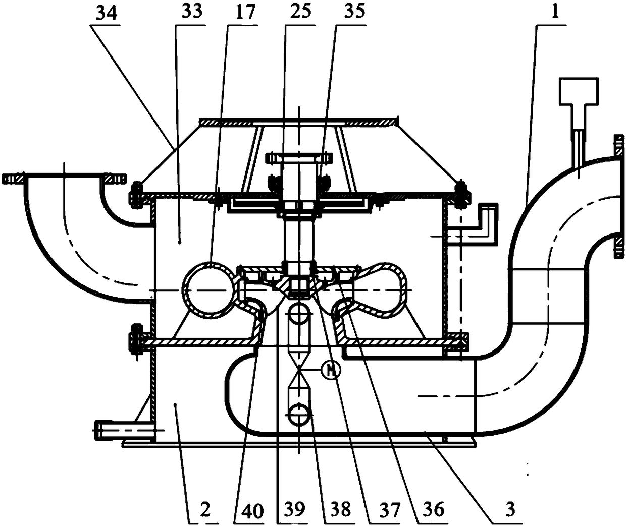
[0060] Low-loss high-efficiency self-priming centrifugal pump, the overall structure diagram is as follows figure 1 As shown, it is mainly composed of a water inlet pipe 1, a water storage chamber 2, a water suction chamber 3, a water pressure chamber pump body 17, an air-water separation chamber 33, an impeller 39, a return pipeline 38 and a mechanical seal device 35.

[0061] The pressurized water chamber is the inner...


PUM


Abstract

The invention relates to a low-loss efficient self-suction type centrifugal pump. The centrifugal pump comprises a pumping chamber, a cross section of the pumping chamber is in a shape of a '6 ' in whole, an outer side edge line is composed of a spiral line A, a curve B and a line C, the line C is connected with the spiral line A and the curve B at the same time and is an intersecting line of theoutlet surface and the cross section of the pumping chamber, an inner edge line is a circle D, a point X is arranged on the line segment, opposite to the curve B, in the spiral line A, meanwhile, thepumping chamber is divided into a strip-shaped T1 section and a ring-shaped T2 section which are in smooth transition connection through a flow passage cross section passing the point X and the intersection point Y, a point S is arranged at the position, close to the point X, on the spiral line A in the T2 section, the flow passage cross sections intersected with the spiral line between the pointY and the point S are coplanar with a circle center E, are in an isosceles trapezoid-like shape, and are gradually increased in area, the area, passing the point S, of the flow passage cross sectionsis the largest, and the hydraulic efficiency of the low-loss efficient self-suction type centrifugal pump is 88% to 97%. According to the pump, full-flow-way hydraulic design is adopted, efficiency, the self-suction performance, the hydraulic performance and the running reliability are balanced, and the application prospect is good.

Description

technical field [0001] The invention belongs to the field of centrifugal pumps and relates to a low-loss and high-efficiency self-priming centrifugal pump. Background technique [0002] The self-priming pump is a centrifugal pump with a special structure. It only needs to be started for the first time to fill water, and then it can be started directly. It has the advantages of convenient use, reliable operation and convenient remote centralized control. But the disadvantage is that the overall efficiency of the pump is low. The existing self-priming pumps are divided into two structures: internal mixing type and external mixing type. The internal mixing type is for the liquid flow back to the impeller inlet, which has a relatively high efficiency. The external mixing type is for the liquid flow back to the impeller outlet, and the efficiency is relatively Low, but the self-priming time is short, but whether it is an external mixing or internal mixing self-priming pump, its ...

Claims


Application Information

Patent Timeline
Patent Type & Authority Applications(China)
IPC IPC(8): F04D1/00F04D9/02F04D29/22F04D29/08F04D29/10F04D15/00F04D29/66
CPCF04D1/00F04D9/02F04D15/00F04D15/0005F04D29/086F04D29/106F04D29/2222F04D29/669
Inventor 赵鹏举陆银华陈招锋程原
Owner 上海瑞晨环保科技股份有限公司
Why Eureka
Try Eureka