Eureka AIR delivers breakthrough ideas for toughest innovation challenges, trusted by R&D personnel around the world.

A quick lock for on-board electronic equipment of tracked armored vehicles

A technology for in-vehicle electronics and armored vehicles, applied in building locks, vehicle parts, transportation and packaging, etc., can solve the problems of low reliability, tripping, large chassis panel area and cabinet volume, etc., to achieve convenient use and operation, in place travel Clear, compact results

Active Publication Date: 2020-02-04
BEIJING INST OF RADIO MEASUREMENT
View PDF6 Cites 0 Cited by
  • Summary
  • Abstract
  • Description
  • Claims
  • Application Information

AI Technical Summary

Problems solved by technology

These two fixing methods have high requirements for the matching accuracy of the chassis and cabinet installation, and the degree of locking depends entirely on the experience of the operator, which may easily cause poor contact of the electrical connector at the rear of the chassis; when it is frequently used and the external vibration is strong, it will also Tripping occurs, affecting the normal use of electronic equipment
In addition, when the chassis is pulled out, it is necessary to leave a space for setting the handle on the panel
[0003] These connection and fixing forms are all in the form of threads, and the stroke is not easy to control. It requires large panel area and cabinet volume, low reliability, and specially made handles, which cannot withstand the harsh vibration environment of tracked armored vehicles.
Cannot be applied to the on-board electronic equipment of tracked armored vehicles loaded with high density

Method used


Image

  • A quick lock for on-board electronic equipment of tracked armored vehicles
  • A quick lock for on-board electronic equipment of tracked armored vehicles

Examples


Embodiment Construction

[0031] The principles and features of the present invention are described below in conjunction with the accompanying drawings, and the examples given are only used to explain the present invention, and are not intended to limit the scope of the present invention.

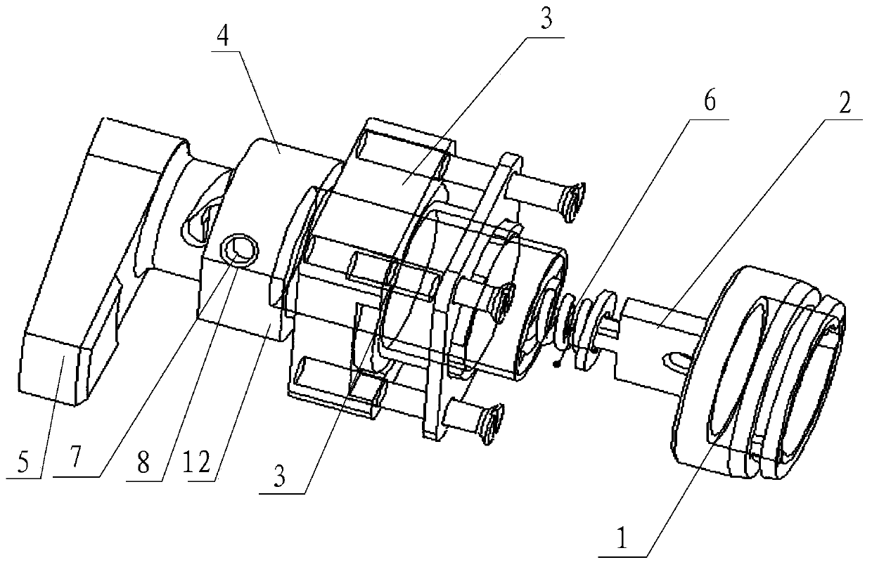
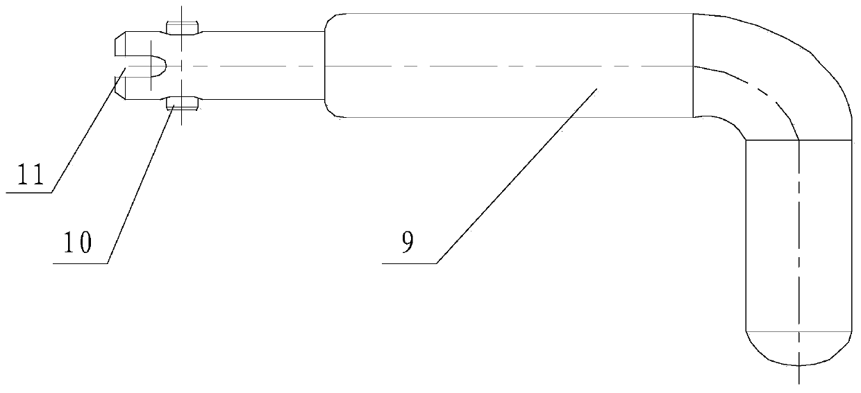
[0032] Such as figure 1 , 2 As shown, a quick lock for on-board electronic equipment of a tracked armored vehicle includes a guide 4, a lock sleeve 3, a lock bolt 5, a positioning member, a lock cylinder 2, a panel locking member 1, an anti-loosening spring 6 and a handle device 9 , the inside of the guide 4 is hollow and open at both ends, the inner wall of the guide 4 is provided with a first positioning groove along its circumference, and the lock sleeve 3 is fixedly sleeved on the outer side of the guide 4, so One end of the lock bolt 5 is recessed inward to form a first groove, and the end of the lock bolt 5 extends into the guide member 4 from one end of the guide member 4, and the positioning member is arran...


PUM


Abstract

The invention relates to a quick lock used for vehicle-mounted electronic equipment of a caterpillar band armored car. The quick lock comprises a guide piece, a lock bolt, a positioning piece, a lockcylinder, an anti-loosening spring and a pulling handle device; the guide piece is hollow, openings are formed in the two ends, a first positioning groove is formed in the inner side wall, one end ofthe lock bolt sinks to be provided with a first groove and extends into the guide piece from one end of the guide piece, the positioning piece is arranged in the guide piece, the lock bolt is clampedor released, the lock cylinder is inserted into the guide piece form the other end of the guide piece and extends into the first groove, the anti-loosening spring is arranged between the lock bolt andthe lock cylinder, one end of the anti-loosening spring abuts against the first groove, and the other end of the anti-loosening spring abuts against the end of the lock cylinder; and one end of the pulling handle device sinks to be provided with a clamping part, a protrusion is arranged on the outer side, the end of the pulling handle device extends into the guide piece to be clamped to the end of the lock cylinder, and locking or unlocking is achieved through positive and negative rotation of the pulling handle device. The quick lock is compact in product structure, clear in stroke, reliablein locking and convenient to use.

Description

technical field [0001] The invention relates to the technical field of a quick lock, in particular to a quick lock used for on-board electronic equipment of a tracked armored vehicle. Background technique [0002] Ordinary vehicle-mounted electronic devices are in the form of chassis and cabinets. At present, the connection and fixing of the chassis and cabinets usually adopt the form of direct fixing and locking mechanism. The direct fixing method adopts drilling and tapping on the vertical beam of the cabinet, directly installs non-falling screws on the chassis panel, and directly screws the non-falling screws into the threaded holes of the cabinet to realize the connection between the chassis and the cabinet. The form of the locking mechanism is usually provided with a hook on the panel, and a locking rod and a disc lock nut are installed on the cabinet beam. When in use, lift the locking lever, turn the disc lock nut to hook it with the hook on the panel, so as to achie...

Claims


Application Information

Patent Timeline
Patent Type & Authority Patents(China)
IPC IPC(8): E05B65/52E05B15/00B60R16/02
CPCB60R16/02E05B15/00E05B65/52
Inventor 周中辉
Owner BEIJING INST OF RADIO MEASUREMENT
Why Eureka
Eureka Blog
Learn More