Mortise capable of limit insertion of main latch and provided with sub latch

A deadbolt and sub-lock technology, which is used in construction locks, locks with spring bolts, and non-mechanical transmission-operated locks, etc., which can solve the problem of reducing the locking function of the deadbolt, unable to forcibly stop the deadbolt, and reducing operational safety. The problem is to prevent the lock tongue locking phenomenon, prevent the door bolt from being stuck, and simplify the operation structure.

Active Publication Date: 2018-11-20
INNO ELECTRIC INC
View PDF4 Cites 1 Cited by
  • Summary
  • Abstract
  • Description
  • Claims
  • Application Information

AI Technical Summary

Problems solved by technology

For example, in the mortise lock of prior art 1, according to the direction of opening the door (that is, opening the door outward or pushing the door inward to open), the operating direction of the push-pull handle will change, and thus the direction of the slope of the mortise lock will also change. (The slope faces indoors or outdoors). Therefore, the internal structure of the mortise lock becomes complicated, which increases the difficulty of making and assembling accessories, reduces operational safety, and increases failure rates.
[0006] In order to solve this problem, the current development of the lock tongue is not linked with the handle, but through the contact between the lock tongue and the door lock, the lock tongue rotates left and right and changes direction to complete the ejection and ejection of the mortise lock (the following is the existing Technology 2), the mortise lock of this prior art 2 is popped in and out through the contact of the door lock buckle, and does not need the rotation of the lock tongue through the handle, but it cannot forcibly stop the lock tongue, so that the lock tongue can freely spring in and out, thus reducing The deadbolt lock function, and when the door bolt is released and the door is tried to open, the door bolt will be stuck due to contact or friction between the door bolt and the door lock. Therefore, it is necessary to forcibly prevent the door from closing. Lock tongue pop-in technology

Method used

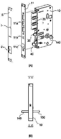
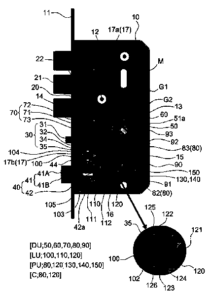
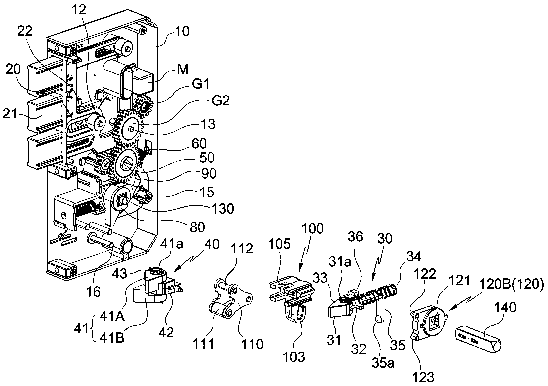

Image

  • Mortise capable of limit insertion of main latch and provided with sub latch
  • Mortise capable of limit insertion of main latch and provided with sub latch
  • Mortise capable of limit insertion of main latch and provided with sub latch

Examples


Embodiment Construction

[0029] Hereinafter, the present invention will be further described based on preferred embodiments with reference to the accompanying drawings. The present invention can have various modifications and various forms.

[0030] But this does not limit the form of the present invention, and all changes, equivalents and even substitutes belonging to the idea and technical scope of the present invention are within the protection scope of the present invention.

[0031] The same reference symbols on the drawings, especially, tens digits and one digits or the same symbols of tens digits, one digits and English letters indicate the same or similar function accessories. If there is no special statement, the drawings indicate The symbol can be regarded as an accessory specified in accordance with the above requirements.

[0032] In addition, for the convenience of understanding, various components on the drawings are enlarged (thickened) or reduced (thinned), but this approach is not in...


PUM


Abstract

The present invention relates to a mortise capable of limit insertion of a main latch and provided with a sub latch, including a dead bolt, a sub latch, a main latch, and a dead bolt operating unit tolock and unlock a door. Specifically, the mortise permits insertion of a latch bolt when the door is open and blocks the insertion of the latch bolt when the door is locked. So, the latch bolt performs a locking function of the door with the dead bolt so that security of the mortise can be improved. To achieve the same, a pressing unit of the sub latch and a pressing protrusion of a latch cam permit a backward movement of a latch transfer while the sub latch half-protrudes due to a closure of the door. So, while the latch stopper rotates in one direction, a locking protrusion blocks the insertion of the latch bolt. When the insertion and the withdrawal of the sub latch are completed as the door is opened and closed by a handle, the pressing unit or the pressing protrusion moves the latchtransfer forward. So, the latch stopper rotates in the other direction, and the locking protrusion permits the insertion of the latch bolt, so that when a door is closed, the main latch is inhibited to be inserted by the mortise; and the main latch is inserted only if the door is opened, so that along with the dead bolt, the main latch itself has a locking function, thereby enhancing security.

Description

technical field [0001] The invention provides a mortise lock with a sub-lock that restricts the ejection of the bolt, including: a bolt, a sub-lock, a deadbolt, and a bolt operation unit. More specifically, after the door is closed, the sub-lock is in the In the out state, the pressure of the pressurizing part and the pressurizing block is released, and the latch limit block moves backward. When the latch brake block swings in one direction, the lock block prevents the spring-in of the lock tongue; through the operation When the handle completes the spring-in and pop-out state of the child lock, the latch limiter moves forward through the pressurization of the pressurizing member or the pressurizing block, and at the same time, the latch brake block swings to the other direction. At this time, the The block begins to disengage, allowing the bolt to snap in. Therefore, when the mortise lock is in the closed state, it prevents the springing of the dead bolt, and only when the d...

Claims


Application Information

Patent Timeline
Patent Type & Authority Applications(China)
IPC IPC(8): E05B63/14E05B17/20E05B15/10
CPCE05B15/10E05B17/2007E05B63/146E05B15/04E05B47/0012E05B47/0603E05B59/00E05B63/08E05B63/14
Inventor 赵阳日
Owner INNO ELECTRIC INC
Why Eureka
Try Eureka