Safe water surface treatment device for oil leakage

A processing device and safe technology, applied in lighting devices, circuit devices, lighting devices, etc., can solve problems affecting the growth of marine plankton, destroying the balance of marine ecology, and hindering the reoxygenation of water bodies, so as to achieve environmental protection, convenience and timely Adjustment, structure simple effect

Inactive Publication Date: 2018-11-20
田康
View PDF3 Cites 1 Cited by
  • Summary
  • Abstract
  • Description
  • Claims
  • Application Information

AI Technical Summary

Problems solved by technology

The formation of oil film can hinder the reoxygenation of water body, affect the growth of marine plankton, destroy the ecological balance of the ocean, and also destroy the seashore scenery and affect the aesthetic v

Method used


Image

  • Safe water surface treatment device for oil leakage
  • Safe water surface treatment device for oil leakage
  • Safe water surface treatment device for oil leakage

Examples


Embodiment 1

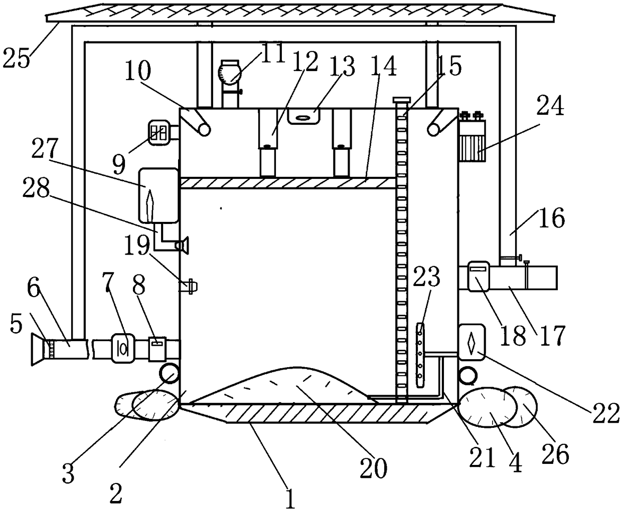
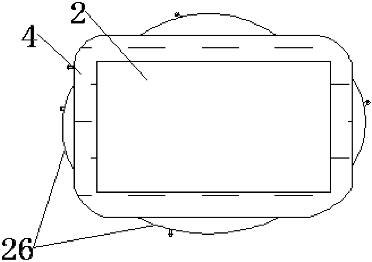
[0018] Example 1: Please refer to Figure 1-3 , an oil spill safe water surface treatment device, including a box body 2, a water inlet pipe 6, a pump 7, a flow meter 8, an LED light 10, a medicine adding pipe 11, a telescopic rod 12, a camera 13, a pressure plate 14, and a water filtration membrane plate 15 , the return pipe 16 and the drain pipe 17, the bottom of the box body 2 is provided with a counterweight 1, the counterweight 1 ensures that the device is stable up and down when it is on water, and prevents the bottom from turning over lightly, and the bottom of the box 2 is provided with Floating ring 4, the upper outer wall of floating ring 4 is provided with auxiliary ring 26, when the work starts, the device is placed in the waters of oil leakage, and the device is floated on the water surface to work by floating ring 4 and auxiliary ring 26, which is beneficial to use, and the box body 2 Both sides of the bottom end are provided with suspension rings 3, the suspensi...

Embodiment 2

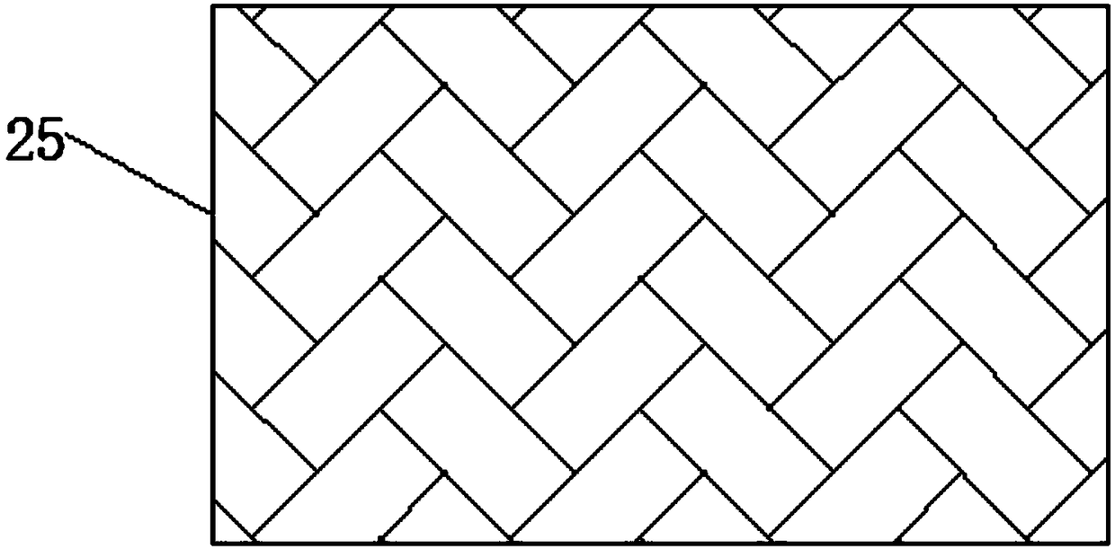
[0019] Embodiment two: on the basis of embodiment one, the top of the box body 2 is provided with a solar roof 25, the solar roof 25 is connected with the storage battery 24 by a lead, and the battery 24 is arranged on the side wall of the box body 2, and the light energy is converted into The electric energy is stored in the storage battery 24, which is beneficial to the work of each electronic component, saves energy consumption, and is beneficial to use.

[0020] The working principle of the present invention is: when the present invention is working, the counterweight ensures the up and down stability of the device when it is on the water, and avoids the bottom from turning over lightly. Floating on the surface of the water, it is easy to use. The ring is fixed by the rope, and the water containing oil is sucked away by the pump in time to avoid its diffusion and increase the degree of pollution. The grid blocks the entry of solid impurities in the water to avoid blocking t...


PUM


Abstract

The invention discloses a safe water surface treatment device for oil leakage. The safe water surface treatment device comprises a box body, a water inlet pipe, a pressing plate, a drain pipe and an igniter, wherein the water inlet pipe is arranged at the bottom end of the box body, a pump and a flow meter are arranged on the water inlet pipe, grids are arranged in the water inlet pipe, the igniter is arranged on the inner wall of the box body, an air bag is arranged at the bottom end of the box body, an oxygen filling tank is mounted on the outer wall of the box body, a breather pipe is arranged on the oxygen filling tank, the breather pipe is provided with two outlet ends, one outlet end of the breather pipe is connected with an air valve of the air bag, the other outlet end of the breather pipe is provided with a spray row, the spray row is arranged in the box body, the side wall of the box body is communicated with an air collector through a suction pipe, a gas one-way valve is mounted on the suction pipe, a water filtration diaphragm plate is arranged in the box body, a telescopic rod is arranged on one side of the water filtration diaphragm plate, and the pressing plate is arranged at the bottom end of the telescopic rod. The safe water surface treatment device reduces oil contamination, facilitates environmental protection, and is simple in structure, convenient to use,and beneficial to popularization.

Description

technical field [0001] The invention relates to an oil treatment device, in particular to an oil spill safe water surface treatment device. Background technique [0002] Petroleum is a viscous, dark brown liquid. There are oil reserves in parts of the upper crust. The main component is a mixture of various alkanes, naphthenes and aromatic hydrocarbons. As an important energy source, oil can be said to be the blood of modern economy. my country is a big oil consumer and the fifth largest oil producer in the world. As a basic industry, the petroleum industry requires a large number of technical personnel. The field of oil production is characterized by high technological content and strong technicality. But oil pollution is also an important issue of concern to the world. Oil pollution refers to the pollution caused by leakage and discharge of oil during oil exploitation, transportation, loading and unloading, processing and use, mainly in the ocean. Oil floats on the se...

Claims


Application Information

Patent Timeline
IPC IPC(8): C02F1/40F23D17/00F21V33/00H02J7/35F21W131/403
CPCC02F1/40C02F2103/007F21V33/00F21W2131/403F23D17/002H02J7/35
Inventor 田康
Owner 田康
Why Eureka
Try Eureka