
Efficient surface joint finish machining equipment

A common and efficient technology, applied in the field of workpiece processing, can solve the problems of affecting polishing efficiency, high labor intensity, and limited functions, and achieve the effects of improving polishing efficiency, reducing labor intensity, and simple structure

Inactive Publication Date: 2018-11-20
广州上同环保科技有限公司
View PDF0 Cites 0 Cited by
  • Summary
  • Abstract
  • Description
  • Claims
  • Application Information

AI Technical Summary

Problems solved by technology

[0002] In some workpiece processing factories, polishing agents are often used to perform finishing operations such as grinding and polishing on the surface of workpieces. Traditionally, too much manpower is required for polishing operations, which is labor-intensive and low in efficiency. There are also existing There are many automatic polishing devices, but their setting modes are relatively simple and their functions are limited. When stirring and mixing the polishing agent, manual operation has to be relied on, which seriously affects the polishing efficiency.

Method used


Image

  • Efficient surface joint finish machining equipment
  • Efficient surface joint finish machining equipment

Examples


Embodiment Construction

[0019] All features disclosed in this specification, or steps in all methods or processes disclosed, may be combined in any manner, except for mutually exclusive features and / or steps.

[0020] Any feature disclosed in this specification (including any appended claims, abstract and drawings), unless expressly stated otherwise, may be replaced by alternative features which are equivalent or serve a similar purpose. That is, unless expressly stated otherwise, each feature is one example only of a series of equivalent or similar features.

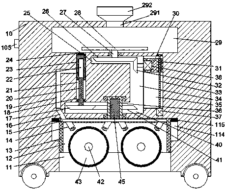
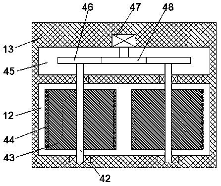
[0021] Such as Figure 1-2 As shown, a kind of high-efficiency common finishing surface equipment of the device of the present invention comprises locomotive 10, and described locomotive 10 top end is provided with mixing cavity 29, and described locomotive 10 bottom end face is provided with the first port downwards. Sliding and pushing cavity 11, the first sliding and pushing block 13 is movably installed in the first sliding and pushing ca...


PUM


Abstract

The invention discloses efficient surface joint finish machining equipment which comprises a locomotive. A blending cavity is formed in the top end of the locomotive, and a first sliding pushing cavity with a downward port is formed in the bottom end face of the locomotive. A first sliding pushing block is movably mounted in the first sliding pushing cavity, and a first rotary bin with a downwardport and a second rotary bin located on the rear side of the first rotary bin are arranged in the first sliding pushing block. First rotary rods are arranged in the first rotary bin in left-right symmetrical and front-back extending modes, the extending ends of the front sides of the first rotary rods are rotatably arranged in the inner wall of the front side of the first rotary bin, and the extending ends of the rear sides of the first rotary rods stretch into the second rotary bin and are connected with the inner wall of the rear side of the second rotary bin in a rotating fit mode. Polishing wheels are fixedly arranged on the first rotary rods in the first rotary bin.

Description

technical field [0001] The invention relates to the technical field of workpiece processing, in particular to an efficient co-finishing surface equipment. Background technique [0002] In some workpiece processing factories, polishing agents are often used to perform finishing operations such as grinding and polishing on the surface of workpieces. Traditionally, too much manpower is required for polishing operations, which is labor-intensive and low in efficiency. There are also existing There are many automatic polishing devices, but their setting modes are relatively simple and their functions are limited. When stirring and mixing the polishing agent, manual operation has to be relied on, which seriously affects the polishing efficiency. Contents of the invention [0003] Aiming at the deficiencies of the above technologies, the present invention proposes a high-efficiency co-finishing surface equipment. [0004] A high-efficiency common finishing surface equipment of...

Claims


Application Information

Patent Timeline
Patent Type & Authority Applications(China)
IPC IPC(8): B24B27/00B24B41/02B24B55/00B24B57/02B24B47/04
CPCB24B27/0076B24B41/02B24B47/04B24B55/00B24B57/02
Inventor 莫洁琼
Owner 广州上同环保科技有限公司
Learn More